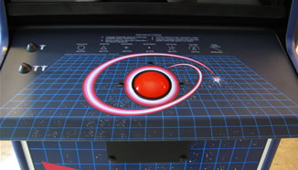
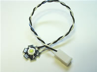
Operation: While the trackball is not moving, the light slowly pulsates. The brightness gradually increases and decreases, sort of like a breathing motion. When you move the trackball, the pulsation speed dramatically increases and the brightness greatly increases. When the trackball stops moving, the pulsations slow down and the brightness goes back down.
Attract Feature: When the trackball or roller is left unmoving for 1 minute, the light "explodes" for a few seconds. This action repeats once per minute.
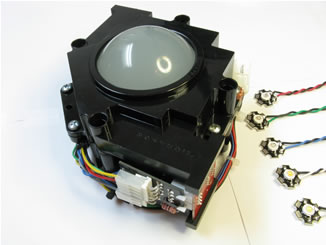
Colors: The BXTLC module is supplied with your choice of one of 5 colors as follows:
- Red : for use with clear and red translucent trackballs
- Green : for use with clear and green translucent trackballs and green Major Havoc roller
- Blue : for use with clear and blue translucent trackballs
- Warm White : for use with clear and any color tinted translucent trackball or roller, looks most like an incandescent lamp,
(recommended for interaction with red, yellow, incandescent lighted surroundings) - Cool White : for use with clear and any color tinted translucent trackball or roller, looks most like natural daylight,
(recommended for interaction with violet, blue, fluorescent, daylight surroundings)
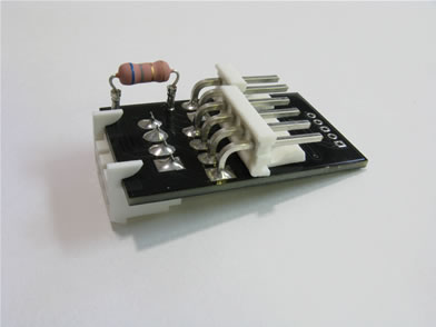
The BXTLC is a direct plug-in add-on module so installation is fast and easy. No extra wiring or soldering is required.
The BXTLC circuit board is designed to plug directly onto the header pins of the existing opto-board of the trackball (or roller) assembly. For a trackball, it doesn't matter on which opto-board (which axis) the BXTLC is installed. Just pick whichever one is the most convenient. For the Major Havoc roller controller, there is only one opto-board (so choose that one).
- Turn off your game.
- Open the control panel.
- If your trackball or roller already has a fixed lamp or LED installed, remove it or unplug it.
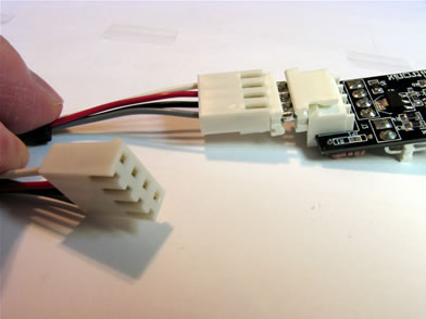
- Carefully unplug the 4-position wiring harness connector from the opto-board.
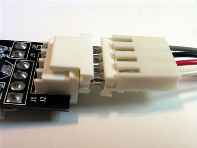
- Plug the BXTLC board onto the opto-board header pins.
- Plug the 4-position female wiring harness connector onto the 4-position male header pins on the BXTLC board.
- Mount the LED supplied with BXTLC in a convenient place on the trackball housing or roller chassis. Refer to pictures.
- Plug the 2-position female connector of the LED wiring harness onto the 2-position male header pins on the BXTLC board.
- Check for any obstructions and make sure that the control panel will close without interference. Secure the LED wiring if needed so that it will not get caught on anything.
- Close the controller panel.
- Turn on the game and observe the new LED is lighted and is cycling. Test by turning the trackball or roller. The LED should get brighter and cycle faster.
- Enjoy!
Opto-Boards, Make sure you have the correct ones:
Before purchasing the BXTLC module, make sure to you check your trackball to make sure that it has the newer Happ style opto-boards and not the old original Atari green opto-boards. The BXTLC will not directly fit the old boards. It can still be used with a simple wiring adapter harness. If your 2.25" Mini-Trak or 3" Midi-Track trackball unit has the newer Happ type boards where the header tab is inbound, the BXTLC will fit normally. The Happ boards can be seen in almost all of the photos shown on the BXTLC pages.
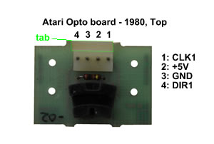
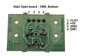
If your trackball has the original Atari opto-boards, the 4-pin header connector is facing the wrong way. The header tab is outbound so it directs the wiring harness connector inward. This turns the BXTLC board inward and hides its 4-pin male header making it inaccessible. In this case, the BXTLC can still be used but it requires a short wiring adapter so that it can be connected. As such, it will not be mounted directly onto the opto-board so you will have to secure it any way that you see fit.
Incorrect Style Opto-board
This is the Atari opto-board produced in 1980. The BXTLC does not fit on this opto-board.
Wiring Adapter (+$5):
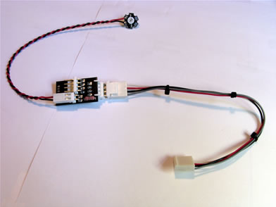
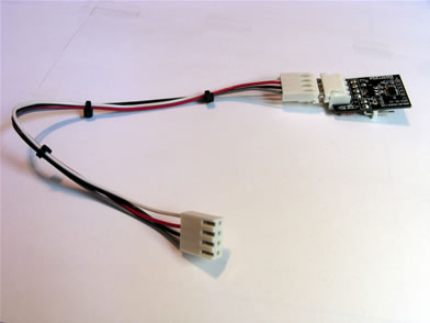
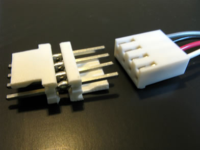
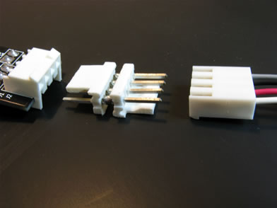
For opto-boards like the one shown above, you can purchase the required wiring adapter for $5 extra. The adapter is a simple male-to-male header followed by a female-to-female wiring extension.
- The control panel harness still plugs directly into the male pins on the BXTLC board.
- The M/M header plugs into the female connector on the BXTLC board.
- The extension harness plugs into the M/M header and the green opto-board.
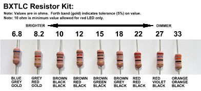
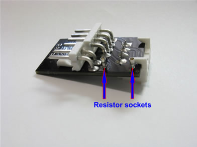
Note: After 2013-05-15: The BXTLC board is shipped with a small assortment of resistors of different values so that the end user can optimize the peak brightness to their preferred level. The PCB will have a pair of small sockets that allow the resistors to be removed and installed without solder or special tools. If you think that the LED is too bright, change the resistor to one of a higher resistance value in order to reduce the LED operating current. If you want it brighter, change the resistor to a lower value.
The following diagram show the values of the resistors that are supplied with BXTLC. Each resistor can be identified by its standard color code bands.
Red LED warning: In order to avoid exceeding the maximum operating power, do not use resistors with a value less then 10 ohms with the red LED. It is safe to use any of the supplied resistor values with the other LED colors.
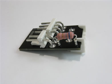
To remove the resistor, grasp it firmly and pull it straight away from the PCB.
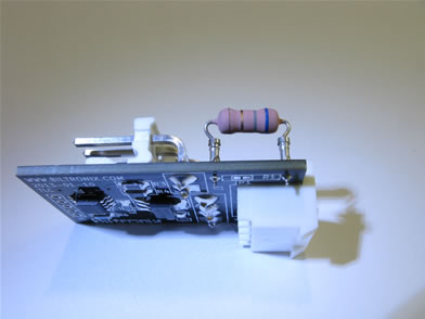
To install a resistor, carefully align its leads with the socket holes and then press them into the sockets.LED resistor value recommendations:
Major Havoc Roller: The roller looks best using the green LED and the 6.8 ohm resistor. If desired, select any higher value of resistor to make it dimmer.
The two most common translucent trackball manufacturers are Happ and Groovy Game Gear. Some Happ trackballs have much less internal light diffusing material than the Groovy Game Gear Electric Ice (GGGEI) ball. As a result, to achieve the same apparent brightness, the BXTLC should be run with a relatively higher resistor value when using a Happ ball than when using the GGGEI ball. It is my personal opinion that the GGGEI translucent trackballs look much nicer then Happ translucent trackballs when lighted.
Recommended default values for trackball LED resistor values:
How The BXTLC Works (Not too technical):
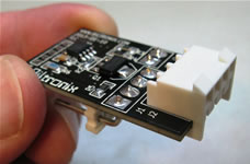
The BXTLC circuit board includes a tiny custom programmed microcontroller and a thermally protected MOSFET lowside driver. The microcontroller chip detects the movement of the trackball or roller by monitoring the opto-board output signals. This does not and will not ever interfere with the proper operation of the trackball or the game itself. The microcontroller then generates a 250 Hz PWM signal that controls the lowside driver. The driver output controls the average LED current and hence the brightness. The brightness of the light is proportional to the driver dutycycle.
Electrical Specifications:
Q & A:
Parameter: Limit: Supply Voltage: +5V (+/- 0.5V) Output Current Limit: 1 A max Output Current with supplied LED: 250 mA max
LED Color : Supplied Onboard
LED Series Resistor Value:Red: 10 ohms minimum Green, Blue, Warm White,
Cool White:6.8 ohms minimum
Q: Will the BXTLC work on Atari Centipede or Millipede?
A: Yes but the exception described above for the original Atari green opto-boards also applies.
Q: Will the BXTLC work on Atari Marble Madness?
A: Yes but you will need two, one for each trackball. Also, the exception described above for the original Atari green opto-boards also applies. The appropriate LED colors would be one red and one blue but of course that is your choice and depends on the ball color.
Q: Will the BXTLC work on Atari Crystal Castles?
A: Yes, however the exception described above for the original Atari green opto-boards also applies. The appropriate LED color would be red but of course that is your choice and depends on the ball color.
Q: Will the BXTLC work on 1980 Atari Missile Command?
A: For the Missile Command cocktail table and the caberet cab, the trackball is a 2.5" mini-trak trackball so the BXTLC can be used however the exception described above for the original Atari green opto-boards also applies.
For the full size upright cab, the BXTLC probably cannot be used. For one thing, on the 4" Maxi-Trak trackball, the opto-board connectors are completely different and so the BXTLC board will not plug into them. While, in theory, a wiring adapter could likely be made, such has never been attempted. Secondly, the 4" trackball is much less common than the smaller sizes. I have never seen a translucent 4" ball available anywhere.
Note: I have no personal experience with the Missile Command fullsize upright machine. If I am mistaken about the trackball size being 4", and if it is actually 4.5", then you can purchase a translucent ball at Happ-Suzo.
Q: Will the BXTLC work on Atari Football?
A: This game used two large black trackballs the same as the fullsize upright Missile Command described above. The same issues apply.
Q: Can the BXTLC drive an incandescent lamp?
A: Yes. To drive a small lamp or a different set of LED's, you must first bypass the on-board series resistor "R1". To do this, simply apply a small blob of solder across the pads of jumper "JP1". Any lamp that you connect must be rated 5V to 6V such as a #555 or #44. Make sure that the total current consumption of the lamp (or lamps) does not exceed the driver output limit of 1A.
Q: Can the BXTLC drive more than one LED?
A: Yes, as for the use of an incandescent lamp as mentioned above, you may have to solder "JP1" in order to bypass the on-board series resistor "R1". Each LED that you connect should have its own series resistor wired in-line with it. Multiple LED's, each with its own resistor, can be wired in parallel. Be sure that the total current draw of all of the LED's combined does not exceed the driver output limit of 1A. It is not recommended to wire multiple LED's in series because there is not enough voltage available from pin J3-1.
Q: What if I want to change the LED (i.e. different color, style, current level)?
A: If your alternative LED has a different forward voltage drop (parameter Vf) or requires a different level of current, you might have to replace the resistor "R1" on the BXTLC board with one of a different value.
Calculate the value of R1 as follows:
R (ohms) = [ Vsupply - LED Vf (V) ] / LED current (A)
Calculate the peak power dissipation of R1 as follows:
Pd (W) = [ Vsupply - LED Vf (V) ] * LED current (A)
Choose a resistor that is rated for at least double the calculated peak power. It is also a good idea to limit the peak resistor power to 2W or less to avoid overheating of the resistor.
Q: Is it possible to drive a string of lamps or LED's connected in series?
A: Yes. The string of lamps or LED's can be powered by an external power supply of higher voltage (higher than the BXTLC +5VDC supply) up to an absolute maximum of 40V. As always, the maximum current draw of all of the externally connected lamps or LED's cannot exceed 1A.
In this configuration, there must be no connection made to pin J3-1. The pin J3-1 is sourced by the game's +5VDC supply, either directly via "JP1" or through the resistor "R1". The pin can be completely isolated by removing the "R1" resistor and making sure that the solder jumper "JP1" is not soldered (open). It is best to simply not wire anything to the pin but in theory, you could solder the pad of J3-1 to a wire that goes to the external supply (i.e. +12VDC) in order to make the J3-1 pin the supply output for the string of lights. Next, connect your string of lamps or LED's such that the (+) positive end is connected to an external power supply such as +12VDC. Connect the (-) negative end to BXTLC output pin J3-2. The maximum current allowed is 1A.
Top ---- Arcade List ---- Home
