|
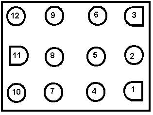
This page describes the procedure for wiring up the power and video connectors. After following these steps, you should be able to plug your Gauntlet board into a JAMMA cabinet and see the attract mode screens. This document assumes that the reader has at least a passing familiarity with crimp-on connectors. I recommend Bob Robert's Crimping Page to those who have never used these connectors before. Wiring up the power connector (PPOWER) This is the most important step of all, and the place where you are most likely to damage your board if you do it incorrectly. I recommend that you double-check all your connections with a multi-meter before applying power to the board (I'll tell you how to do this later on). You'll need the 12-pin Amp Mate and Lok connector, and some 18-gauge wire. You can use 20-gauge wire, but I prefer to use 18-gauge for the power and ground lines to minimize the voltage drop due to resistance in the wires. For the power and video connectors, I like to use wire colors that match the signal (RED = +5V or Red video, BLACK = GROUND, GREEN = Green video). Using different colored wires makes keeping track of where each wire goes much easier when hooking up your connectors to your JAMMA fingerboard. The first thing to do is figure out how long your adaptor wiring will need to be. Put the Gauntlet board in your cabinet, and roughly measure how long the wires need to be to connect the power connector to the JAMMA edge connector. Then, cut all your power wires to that length. Looking down at the PPWR connector on the board, here are how the pins are numbered (remember, this is the pinout on the board, not on the connector you are making):
Here's how to wire it up:
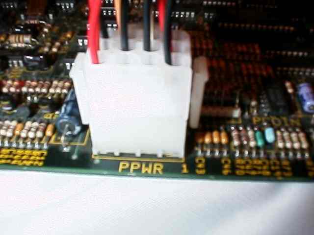
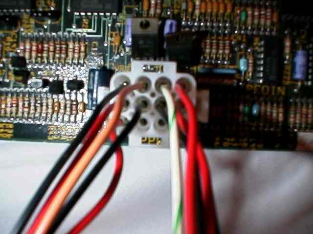
Here's how it should look when you are done - you can see pins 4 and 7 are empty, and pins 6 and 9 have the WHITE-GREEN and ORANGE wires, to help you orient yourself.
The Gauntlet pinouts on spies.com show +15VDC and -15VDC on pins 6 and 9. I just hook these up to +12 and -5VDC respectively, as you can see in the table above. They also show +SENSE on pin 2, and -SENSE on pin 5. You can leave these unconnected, but they are connected to the +5V and GROUND rails on the board, so I chose to connect them to +5V and GROUND as well. So, crimp on your molex connectors, solder the other ends of the wires to the finger board, and you are done. What I like to do at this point is go through with a multimeter and make sure I haven't screwed anything up. Plug your connector onto the board, but don't plug the fingerboard into your cabinet yet. Now, use a multimeter to check check connectivity - the ground connections (1,2,A,B) on the fingerboard should all be connected together on the board, so double check this with the meter. If they aren't, then your connector is miswired. Ditto for the +5V wires (3,4,C,D). Finally, make sure that there are no shorts between the +5V, GROUND, -5V and +12V lines (there should be no connection between these lines). If you really really want to be careful, you can pick one of the 14-pin chips on the board, and make sure that pin 7 on the chip is connected to your GROUND wires, and pin 14 is connected to your +5V wires. When you finish, you can put some wire ties along the length of the wires to hold them together in one tidy package. That's it! You are done with the power connector! Wiring up the video connector (PVID) This is the first of several .100 inline Molex connectors you will have to build. 22 gauge wire works best with these connectors, but you can also use 20 gauge wire, and even 18 gauge in a pinch (it's a little hard to crimp the larger wires, but once they've been crimped, they will fit in the connector housing just fine). Each of these Molex connectors has a "key" pin to help make sure that you plug the connector in correctly. What I did was break off the tip of a toothpick in the connector housing in all the unused and key connector holes to make sure that they line up with the missing pins on the PCB. For example, you need an 11-pin connector to plug into the PVIDEO header - all I had was 12-pin connectors, so I broke off the tip of a toothpick in the unused 12th pin socket, and also in the 3rd pin socket, which lines up with the "key" pin in the PVIDEO header. Now it is impossible to plug that connector in the wrong way. Here's how to wire it up:
When you are done, it should look something like this: 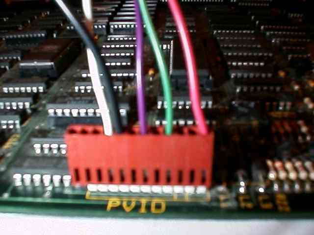
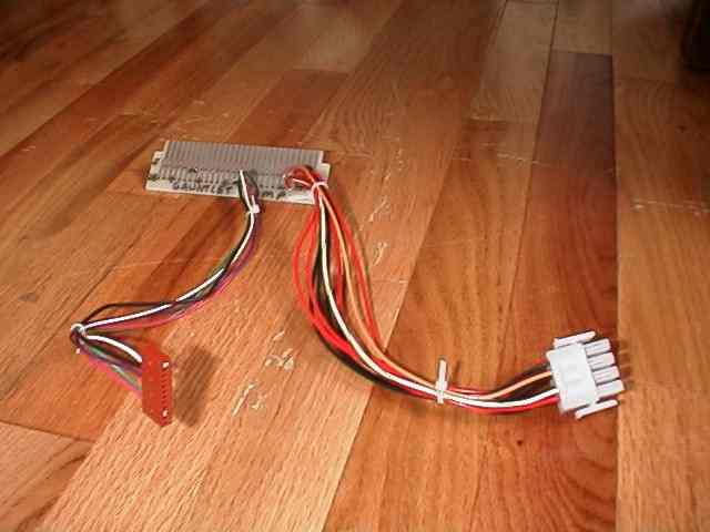
Note that there are several Ground connections on the PVID connector. I grabbed one of them to connect to the video ground on the JAMMA fingerboard, but I ignored the rest. Gauntlet is a big PCB, so in an attempt to keep an even ground at all parts of the board, I connected one ground wire from each connector to a ground tab on the fingerboard, as you will see. Theoretically, the only ground wires you need to connect are from the PPOWER connector, but it can't hurt to run some extra ones. If you want to double check your work here, you can make sure that the ground wire on your connector is really connected to ground (has continuity with one of the ground pins on the PPOWER connector). It's not a good idea to connect one of your video outputs to ground, but other than that it's pretty hard to do any damage by miswiring this connector. When you are done, put some wire ties on the wires that go to this connector to hold them together in a nice neat package. You should end up with something like this:
Testing your PCB OK, you've got your power connector and your video connector, so you are ready to test out your PCB! Go plug the fingerboard into your JAMMA edge connector (make sure you've marked the "COMP" and "SOLDER" sides correctly, so you plug it in the right way). Turn on your cabinet, and bask in the glory of Gauntlet! If it didn't work, I don't know what to tell you. Here's a few obvious things to check. 1) Check if the LED is lit up on the board. If it isn't, you might
not have power (bad crimp on the power connector? Shorted power lines
leading to a blown fuse in the cab?). For the purposes of the rest of the document, we'll assume that the Gauntlet video came up OK, and so you have a working board. Click here to go on to wire up the controls and the coin switches... Last updated on July 1, 2002 |