|
This page describes the procedure for wiring up the connectors for the joysticks, buttons, and coin switches. After following these steps, you should be able to play Gauntlet on your JAMMA cabinet (without sound, of course). This document assumes that the reader has at least a passing familiarity with crimp-on connectors. I recommend Bob Robert's Crimping Page to those who have never used these connectors before. Wiring up the Player 1 and Player 2 connectors (PPL1/PPL2) This connector should go pretty quickly, since you already have experience with putting together the PVIDEO connector. Again, I recommend using 22 gauge wire, although I used 20 gauge wire for mine because I did not have any 22 gauge. You'll need an 11 pin inline Molex connector, similar to the one you used for the PVIDEO connector. IMPORTANT: You can use a 12-pin connector, but you'll have to cut off one of the extra pin housings, because there is not enough room between the PPL1/2/3/4 connectors for the extra 12th pin housing. As with the PVIDEO connector, I broke a toothpick off in the "Key" housing to make sure it was impossible to plug this connector in the wrong way. I just used all the same color for the control wires, because I didn't think that making them different colors would help me remember which wire carried which signal (unlike the PVIDEO connector, where it's pretty easy to remember that the green wire carried the green video signal). Also, since the Gauntlet "Start" button is also the "Magic" button, I wired up Button 2 from the JAMMA control panel to that line, instead of the JAMMA Start button. This allows us to use the JAMMA Start buttons to enter credits, if we desire. I'll cover this in more detail when I describe how to wire up the PCOIN connector. One last tip: The order of the connections is exactly opposite of their order on the JAMMA fingerboard. See the chart below to see what I mean (notice how the "Position on JAMMA fingerboard" column shows the control signals to come from consecutive tabs). This makes it easy when wiring up the connector to the fingerboard, so you don't constantly have to refer to the pinouts. Here's how to wire up the PPL1 connector:
Wiring up the PPL2 connector is similarly easy:
When you are done, it should look something like this (I left an extra pin housing on the right side of the P1 connector, because there was room for it): 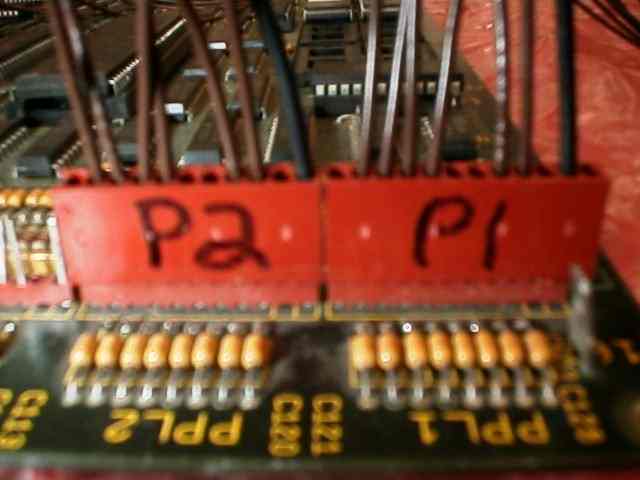
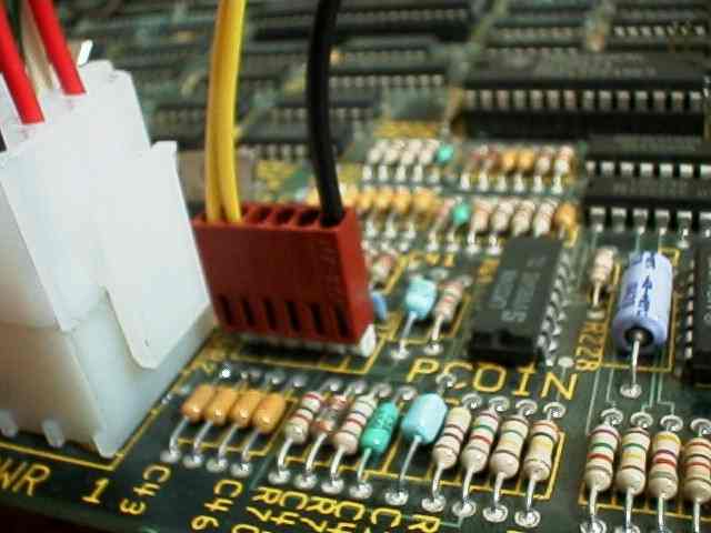
I didn't bother double-checking my wiring on this one. It's pretty hard to screw anything up, since you are just wiring up switches - even wiring the ground wire up to one of the switch wires won't do anything bad. If you accidentally have one of the wires crossed, it's easy to swap them at the Molex connector. You'll want to put cable ties on the wires going to each connector after you get them all soldered to the fingerboard, or you'll end up with a big tangled nest of wires. If you have a Gauntlet II PCB or a 2-player Gauntlet PCB, you are done. You can select which player you want when starting a game, so you don't ever have to swap the controls. However, if you have a regular 4-player Gauntlet 1 PCB, you have a problem, because the only way to play the Elf and the Wizard is to plug your P1 and P2 housings into the PPL3 and PPL4 headers on the PCB (the pin orderings are all identical). I'll leave how to resolve this as an exercise to the reader (it really depends on how complex you want to be), but I'll give you some suggestions: 1) Whenever you want to change players, manually unplug the associated connector from the PCB and plug it into the correct header. It should be OK to do this while the PCB is powered up (you are just disconnecting switches), but I make no guarantees about this - to be 100% safe, turn off the game first. This is the simplest option, and is a good option if you have ready access to your PCB. 2) Hook the wires up to some sort of a switch (say, one of those little switchboxes for manually switching a parallel port between two printers), so you can just turn a dial to determine which character's controls you are connected to. 3) Wire up the P1 connector to your favorite character (say, the Warrior) and wire up the P2 connector to all 3 of the other controls (in this case, PPL2, PPL3, and PPL4). P1 will always be the Warrior, but P2 can control any other character - just make sure that you wire up your PCOIN connector so you only coin up the character that P2 wants to play. So, for example, when P2 presses the Start/Magic button, it's as if he pressed the Start button for the Elf, the Wizard, and the Valkyrie, but if you've only coined up the Wizard, then the presses for the Elf and the Valkyrie will be ignored, and it'll be as if P2 is only connected to the Elf connector. If anyone has other solutions to this issue, please let me know! Hooking up the PCOIN connector Hooking up the PCOIN connector is pretty straightforward, depending on what kind of PCB you have. If you have a Gauntlet II or 2-Player Gauntlet PCB, you'll probably want to just connect the coin switch inputs to the JAMMA 1- and 2-player Start buttons - that way you can insert credits/add health just by pressing the 1- and 2-player Start buttons. You could also just connect them to the JAMMA coin switches, if you want to run your game for money. If you've got a regular 4-player JAMMA PCB, then you may want to consider other options, depending on how you handle the "select a player" problem described above. Many people just connect all the coin switches to the JAMMA coin switch (or to one of the Start buttons) so they coin up all the players at once, and then just control whichever characters they've connected the controls to. If you go with option 3 above, you may need to be able to coin up players individually, which you can do by making your own switches, or by connecting the 4 Gauntlet switches to 4 unused switches on your cabinet (for example, the 2 JAMMA start buttons and 2 coin switches). There are lots of possibilities, but I'll show the simple case below (2-player Gauntlet PCB or Gauntlet 2). You'll need a 6-pin .100 inline Molex connector for this. As always, I break off a toothpick in the "Key" housing to prevent plugging the connector in the wrong way. Here's how to wire it up for Gauntlet II or a 2-player Gauntlet PCB:
Here's how it should look when it's done:
That's it - your Gaunlet game should now be playable (albeit without sound). Have fun! Click here to go on to wire up the sound and test switches... Last updated on July 1, 2002 |