The restoration process continued:
Electronic Repairs:
Power Supply:
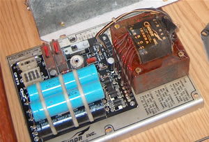
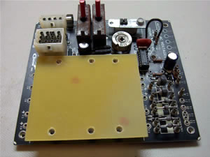
As with most big projects, I started with the power supply, the first step being a thorough cleaning. Next, I hand painted the exterior of the big transformer black. It had been very rusty so I used a wire brush to scrub off the rust. A typical power supply rebuild includes replacement of the big capacitors and usually a regulator chip and its socket. I went a little farther buy replacing all of the old diodes, resistors, transistors, and fuses and their holders. I couldn't source those old style big long cylindrical electrolytic capacitors so I used some high quality radial ones. That required me to make some sort of support for them so I made a plate and mounted it with aluminum 1/4" by 1/2" hex standoffs located at holes that already existed in the main board.
This is the original power supply made by Condor. Note the large blue capacitors and the rusty transformer.

Here's the board after replacing resistors, capacitors, diodes, the regulator IC & socket, and installing the hex standoffs.
Here's the mounting plate that I made for the new capacitors. It was secured with 6-32 machine screws.

Here's the finished power supply mounted in the machine. If I ever manage to find a source for new capacitors that are axial like the originals, I can easily removed my "cap mod" to install them.
If you have to replace the big power transistor on your power supply, you might find that its part number is one of several different devices that were factory installed. The most common is the 2N6055. Sometimes you will find the 2N6577. It might be something else. This list applies to Condor, Data Power, National Power Technology, and Xentek power supplies.
2N6055: NPN darlington, Vce = 60V, Ic = 8A, hfe = 750/18000, ft = 4 MHz, case = TO3
Here is a list of several devices that you can safely replace the 2N6055 with:
2N6284 : 100V, 20A, STMicro
2N6578 : 120V, 15A, GE, Central Semi, Inchange Semi
2N6577 : 90V, 15A, GE, Central Semi, Inchange Semi, Semelab, Motorola
2N6576 : 60V, 15A, GE, Central Semi, Inchange Semi
I have not tested the following devices but their datasheets indicate that they would work:
2N6056 : 80V, 8A
2N6057 : 60V, 12A
2N6058 : 80V, 12A
2N6059 : 100V, 12A
2N6282 : 60V, 20A
2N6283 : 80V, 20A
2N6384 : 60V, 10A
2N6385 : 80V, 10A
2N6576 : 60V, 15A
Game Boards:
Many Cinematronics games consist of two main circuit boards, the CCPU (game computer) and the audio board (produces all sounds). The same CCPU board was used in many games, the only difference being the code programmed into the eproms. The audio board was different for each game. All of the CCPU based games used the same connectors to hook up to power and the other boards. The CCPU board uses 3 flat ribbon cables to connect to the audio board, the control panel, and the monitor. The connectors on these cables use insulation displacement to make the connection. These so-called IDC cables can be degraded by oxidation between the connection blades inside the connector head and the wire conductors in the cable. Even if the cable looks clean on the outside, the oxides can prevent connection. Complete replacement of the cables and the connectors is recommended. It is also a good idea to replace the headers on the PCB's but do not attempt this unless you know what you're doing and have the correct tools or you will only end up permanently damaging the boards. The widest ribbon cable (similar to that used to connect a standard PC floppy disk drive to the motherboard) connects the CCPU board to the digital X-Y monitor. This is the most critical connection because the monitor will not run properly if this connection is not reliable.
The most difficult aspect of repairing a Cinematronics game is that you will have a very difficult time troubleshooting the CCPU board or the monitor board if the other one isn't working. In my case, neither one was working, so I decided to work on the audio board first.
Audio:
You can connect power to the audio board and using a few wires and by following the procedure in the original manual, you can make it produce all of the individual games sounds. The logic circuits of the audio board are relatively simple so they are straight-forward to fix. The logic circuits consist of a simple shift register and latch. The rest of the circuits vary depending on the game, but many consist of simple oscillators based on 555 timer chips. All the sounds are mixed through a resistor network and a discrete component amplifier drives the speaker. The amplifier is driven by plus/minus 28 VDC supplies that are regulated down to plus/minus 15 VDC by simple 7815 and 7915 3-pin regulators.
CCPU:
One can troubleshoot the CCPU board, at least to a point, without a working monitor. The fact is that if the CCPU board isn't running properly, it almost surely will not send valid data to the monitor anyway and that will cause the monitor to draw too much current and make the breakers pop. Professional repair services provided for the CCPU board used a complex piece of equipment called a "signature analyzer" to quickly zero in on the faulty component. Without such a tool, it is very difficult to troubleshoot a CCPU board. My approach is to perform a detailed visual inspection, replace anything that appears suspect, and then I start replacing chips. It helps to have a few spare boards lying around because they can be a source of chips for swapping. It also helps to have a good universal chip programmer on hand with which to verify or program eproms and bipolar proms. You can be relatively sure that the CCPU board is running correctly when it will coin up and play blind.
My CCPU board got the full treatment, cleaning, new eproms, some new bproms, new capacitors, and new ribbon cable headers. That was fortunately enough to get it running. The monitor on the other hand was a different story.
Continue to Star Castle page 3 of 8, the monitor
Back to Star Castle page 1 of 8
Arcade List ---- or ---- Home