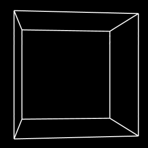
The hull mesh data in the various 8-bit versions of Elite seem to be about the same. The Apple II and C64 data is byte-for-byte identical in most cases, though the Apple II version re-uses some edge and face data, and lacks the Cougar. See the Ship Characteristics page for a complete list.
In the Apple II version, the hull definitions start at $A300, and run almost to the end of the file (about 7.1KB).
Hull definitions start with a 20-byte header, and are followed by a list of vertices. In most cases this is followed by the edges and faces, but for some ships the edge/face data from another mesh is used.
Using the Escape Capsule as an example:
 +00   $20    ;high nibble is scoop info, low nibble is debris spin info
 +01   $0100  ;two-byte missile lock data
 +03   $2c    ;low byte of offset to edge data
 +04   $44    ;low byte of offset to face data
 +05   $1d    ;(4 * maxlines + 1) for ship lines stack
 +06   $00    ;gun vertex * 4
 +07   $16    ;explosion count, 4*n+6
 +08   $18    ;vertex count * 6 (byte count)
 +09   $06    ;edge count
 +0a   $0000  ;bounty value (0.1 Cr units)
 +0c   $10    ;face count * 4 (byte count)
 +0d   $08    ;LOD distance; past this it's just drawn as a dot
 +0e   $11    ;hull strength ("energy")
 +0f   $08    ;speed
 +10   $00    ;high byte of offset to edge data
 +11   $00    ;high byte of offset to face data
 +12   $04    ;down-scaling of normals (larger value -> smaller ship)
 +13   $00    ;00LLLMMM, where LLL is laser power, MMM is # of missiles

Vertices:
 +0/1/2: unsigned X/Y/Z value
 +3: flags XYZV VVVV
     X/Y/Z = 1 if coordinate value is negative
     VVVVV = visibility cutoff
 +4/5: four face indexes (one per nibble), for visibility test
     (if fewer than 4 are relevant, one is repeated)
 .bulk   $07,$00,$24,$9f, $12,$33 ;-$07, $00, $24 / faces 1,2,3
 .bulk   $07,$0e,$0c,$ff, $02,$33 ;-$07,-$0e,-$0c / faces 0,2,3
 .bulk   $07,$0e,$0c,$bf, $01,$33 ;-$07, $0e,-$0c / faces 0,1,3
 .bulk   $15,$00,$00,$1f, $01,$22 ; $15, $00, $00 / faces 0,1,2

Edges:
 +0: flags 000V VVVV
     VVVVV = visibility cutoff
 +1: two face indices (one per nibble), for visibility test
 +2/3: vertex index * 4
 .bulk   $1f,$23,$00,$04 ;vertices 0,1 / faces 2,3
 .bulk   $1f,$03,$04,$08 ;vertices 1,2 / faces 0,3
 .bulk   $1f,$01,$08,$0c ;vertices 2,3 / faces 0,1
 .bulk   $1f,$12,$0c,$00 ;vertices 3,0 / faces 1,2
 .bulk   $1f,$13,$00,$08 ;vertices 0,2 / faces 1,3
 .bulk   $1f,$02,$0c,$04 ;vertices 3,1 / faces 0,2

Faces:
 +0: flags: XYZV VVVV
     X/Y/Z = 1 if coordinate value is negative
     VVVVV = always-visible cutoff
 +1/2/3: face normal x/y/z
 .bulk   $3f,$34,$00,$7a ; $34, $00,-$7a
 .bulk   $1f,$27,$67,$1e ; $27, $67, $1e
 .bulk   $5f,$27,$67,$1e ; $27,-$67, $1e
 .bulk   $9f,$70,$00,$00 ;-$70, $00, $00
The data format effectively limits shapes to 64 vertices, 42 edges, and 16 faces.
It's common for mesh definitions to be structured as a list of vertices and a list of faces, where each face is a list of vertex indices. Because this is focused on wireframes, and the authors wanted to support slightly-non-convex shapes, This works differently.
There is still a list of vertices, but what's drawn is a list of edges. Each vertex has a set of 1-4 associated faces, and each edge has a set of 1-2 associated faces. Each face is just a normal vector used to determine visibility for backface removal. For each vertex and edge, if at least one associated face is visible, the item is considered visible.
This arrangement allows the code to quickly discard vertices that aren't part of a visible edge. It also provides a way for edges that aren't part of a face, e.g. the prongs on the Krait, to be excluded: if the two nearby faces aren't visible, the prong isn't drawn. (It's not perfect, but at 280x192 you'll never notice.)
If the ship is very far away, it's not drawn. If it's closer but still too far to have a distinct shape, determined by the Level of Detail (LOD) value, it's drawn as a dot. When it's close enough to see clearly, the distance is compared to the 5-bit visibility limit that is encoded into each vertex and edge. If the distance is greater than the limit, the element is not drawn. This provides a second LOD test, allowing fine details (like the cabin window on the Krait) to be excluded while the ship is still far away.
The visibility limit works differently for faces: if the ship is outside the visibility limit, the face is *always* visible, regardless of backface tests. You can see this used on the "plate / alloys" hull, which has a single face that is always visible (limit=0).
Of possible interest are the original shape definitions (.zip). For other formats such as VRML, see the Elite Archives.
3D coordinate systems can be left-handed or right-handed. If you follow the standard Cartesian practice and have +X toward the right and +Y toward the top, you can choose to have +Z go into the screen or out of it.
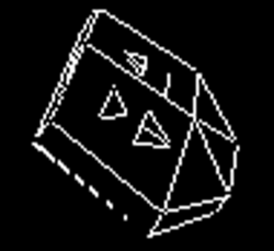
The Transporter is special in that it isn't symmetric across the X axis. The authors put their initials (IB and DB) on the top panels of the ship (image from Elite Wiki):
 .
.
By examining the hull definition we can determine which coordinate system the ship was designed in.
Looking at the shape definition, the initials are on faces 6 and 7. Face 6 is DB, and has surface normal [8,32,3], so it's facing toward +X. Face 7 is IB, and has surface normal [-8,20,3], so it's facing toward -X. To be legible to a viewer on the side of the ship, DB should be on the starboard side, and IB should be on the port side. This gives us +X on the starboard side, +Y up, and +Z at the front, which means it's defined in a left-handed coordinate system.
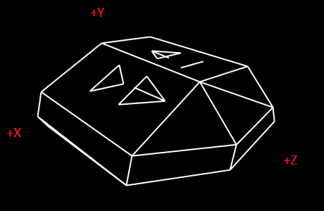
SourceGen expects a left-handed coordinate system, so the mesh vertices don't need to be adjusted.
Elite determines whether a face is visible using only the data in the faces table, which consists primarily of a surface normal. Doing it this way, rather than transforming vertices and testing for whether they appear in clockwise order, is more efficient because it allows us to avoid transforming a potentially large number of vertices. It also allows shapes that are otherwise convex to have protrusions, such as the prongs on the Cobra Mk III and Krait.
In an orthographic projection, a surface normal alone is sufficient to determine face visibility, by simply checking whether the transformed normal vector points toward or away from the camera. For a perspective projection this isn't enough. To understand why, consider a cube that is rotated 6 degrees about the Y axis. The front face is visible, the back face is not, and none of the sides should be. But the Z component of the normal vectors for the left and right sides point toward and away from the view plane, so with a simple Z test we'd conclude that the left face was visible. We want to avoid drawing them until the face is at least edge-on to the camera.

What we need to do is calculate a vector from the camera to any vertex on the face, and then check the angle between that and the surface normal. As the cube rotates the angle changes until the surface becomes edge-on, which is the threshold of visibility, and corresponds to an angle of 90 degrees. We can compute this with the dot product. (This approach is described on the wikipedia page.)
Elite manages to do back-face culling without consulting the list of vertices. How?
Consider the tetrahedral Escape Pod:
Vertices:
 0   $07,$00,$24,$9f, $12,$33 ; -7, 0, 36 / faces 1,2,3
 1   $07,$0e,$0c,$ff, $02,$33 ; -7,-14,-12 / faces 0,2,3
 2   $07,$0e,$0c,$bf, $01,$33 ; -7, 14,-12 / faces 0,1,3
 3   $15,$00,$00,$1f, $01,$22 ; 21, 0, 0 / faces 0,1,2

Edges:
 0   $1f,$23,$00,$04 ; vertices 0,1 / faces 2,3
 1   $1f,$03,$04,$08 ; vertices 1,2 / faces 0,3
 2   $1f,$01,$08,$0c ; vertices 2,3 / faces 0,1
 3   $1f,$12,$0c,$00 ; vertices 3,0 / faces 1,2
 4   $1f,$13,$00,$08 ; vertices 0,2 / faces 1,3
 5   $1f,$02,$0c,$04 ; vertices 3,1 / faces 0,2

Faces:
 0   $3f,$34,$00,$7a ; 52, 0, -122  (edges 1,2,5 = vert 1,2,3)
 1   $1f,$27,$67,$1e ; 39, 103, 30  (edges 2,3,4 = vert 0,2,3)
 2   $5f,$27,$67,$1e ; 39, -103, 30 (edges 0,3,5 = vert 0,1,3)
 3   $9f,$70,$00,$00 ; -112, 0, 0   (edges 0,1,4 = vert 0,1,2)
The direction of the face normals is perpendicular to the face, and the magnitude reflects the distance from the origin. We can confirm that this is the case with a bit of math.
The plane equation can be found by treating two edges as vectors and computing their cross product. In Elite, some faces have more than three vertices, but the game designers ensured that they were coplanar. So the choice of which edges to use doesn't matter.
Edge vectors are created by subtracting the two vertices associated with an edge. For the six edges:
v0 - v1 = [-7, 0, 36] - [-7, -14, -12] = [0, 14, 48]v1 - v2 = [-7, -14, -12] - [-7, 14, -12] = [0, -28, 0]v2 - v3 = [-7, 14, -12] - [21, 0, 0] = [-28, 14, -12]v3 - v0 = [21, 0, 0] - [-7, 0, 36] = [28, 0, -36]v0 - v2 = [-7, 0, 36] - [-7, 14, -12] = [0, -14, 48]v3 - v1 = [21, 0, 0] - [-7, -14, -12] = [28, 14, 12]Computing the cross product gets us the plane normals, which we can confirm match the values from the face table if you multiply them by a scalar value:
e1 x e2 = [0,-28,0] x [-28,14,-12] = [336,0,-784] ~= [52,0,-122] * 6.43e3 x e2 = [28,0,-36] x [-28,14,-12] = [504,1344,392] ~= [39,103,30] * 13.05e3 x e0 = [28,0,-36] x [0,14,48] = [504,-1344,392] ~= [39,-103,30] * 13.05e1 x e4 = [0,-28,0] x [0,-14,48] = [-1344,0,0] ~= [-112,0,0] * 12(The scalar value doesn't matter here. We're just confirming that the normal vector we generate from edges has the same direction as what's encoded in the data file.)
So what about the magnitude of the normal vector? It should represent the
distance of the face's plane from the origin. We start by finding the
planes for each face. The plane equation is Ax + By + Cz = D,
where the normal vector we calculated above provides [A,B,C]. We can plug
in any associated vertex [x,y,z] to get D.
v1[-7,-14,-12] --> 336x + 0y + -784z = 7056v0[-7,0,36] --> 504x + 1344y + 392z = 10584v0[-7,0,36] --> 504x + -1344y + 392z = 10584v0[-7,0,36] --> -1344x + 0y + 0z = 9408Now we apply the formula for finding the distance from a plane to a point:
dist = abs(A*x + B*y * C*z + D) / sqrt(A*A + B*B + C*C).
Because we're measuring the distance to the origin, [x,y,z] is [0,0,0],
which simplifies things greatly.
abs(7056)/sqrt(336*336 + 0*0 + -784*-784) = 8.27abs(10584)/sqrt(504*504 + 1344*1344 + 392*392) = 7.11abs(10584)/sqrt(504*504 + -1344*-1344 + 392*392) = 7.11abs(9408)/sqrt(-1344*-1344 + 0*0 + 0*0) = 7.0Our expectation is that the magnitude of the face normal vectors is a multiple of the distance of the plane from the origin. Let's check:
sqrt(52*52 + 0*0 + -122*-122) = 132.62; 8.27 * 16 = 132.32sqrt(39*39 + 103*103 + 30*30) = 114.15; 7.11 * 16 = 113.76sqrt(39*39 + -103*-103 + 30*30) = 114.15; 7.11 * 16 = 113.76sqrt(112*112) = 112; 7 * 16 = 112So for this hull definition, the magnitude of the normal is approximately equal to the distance of the plane multiplied by a (convenient) factor of 16. The approximation is due to values being stored as integers. The net effect is that the vector represents the point on the surface's plane that is closest to the origin (which is where our camera is).
TODO: test relationship between normal multiple of 16 and the down-scale factor of 4 in the hull definition. (For Escape Capsule the value is 4, and 2^4 = 16.)
The README for Elite: The New Kind lists, in the Known Problems section, "Bits of hidden surfaces on ships sometimes show through". The project faithfully recreated the original algorithms, so this seemed odd. When I started rendering the shapes with SourceGen I also noticed a number of issues, which are explored here.
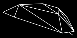
If you view the Cobra Mk III rotated to X=330 Y=233 Z=0, the ship looks correct. If you rotate one more tick, to Y=234, one of the edges vanishes:
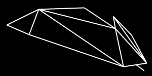
We can get the edge number from an annotated copy of the top view of the ship:
Edge #7, drawn from vertex 5 to vertex 9, is disappearing. Looking at the data file, edge 7 is visible when either face 5 or 9 is visible. Vertex 5 has no visibility constraints, and vertex 9 is visible when face 5, 6, or 9 is visible. Face 9 is the back side of the ship, which is facing away from the viewer, so for our current orientation the edge is drawn whenever face 5 is visible. Which it clearly is. So what's the problem?
Visibility is determined by surface normals. The normal vector for
face 5 is [-14,47,0]. Normalized to a unit vector, it's
[-0.29,0.96,0.00]. Let's compare that to what we get by
computing it from the cross product of the edges.
Face 5 has three vertices: 2, 5, 9.
The vector from 2 to 9 is [0,26,-40] - [0,26,24] = [0,0,-64],
the vector from 9 to 5 is [0,26,24] - [-88,16,-40] = [88,10,64].
The cross product is [640,-5632,0], which normalizes to
[0.11, -0.99, 0.00].
We took the vertices in the wrong order, so the sign is flipped. If we flip it and take the dot product of the two vectors, then compute the angle with the arc-cosine, we get a value of 10 degrees, which is a pretty significant difference. So the edge looks wrong because the data is wrong.
How do we fix this? By rewriting the surface normals. This is a little awkward because Elite doesn't store faces as a list of vertices. We can figure out which edges and vertices are associated with each face by looking through the vertex and edge lists, but there's a problem. The laser turret on the front of the ship is edge 22, drawn when either face 0 or 11 is visible. However, the edge isn't actually part of either face, and would throw off our calculations if we tried to use it.
How can we avoid this problem? By using the level-of-detail threshold as a hint. The top lines of the ship use level $1F or (for edges 20/21) $1D. The laser turret uses $06, and most "decorations" are at the same level. By ignoring anything below a certain threshold we should be able to avoid including "decorations" in face computations. If we use the vertices in the wrong order, as we did earlier, we can detect the problem by simply checking to see if the vector points toward or away from the shape's center.
This leaves the question: why are they wrong? Most likely it's an error, but it could be deliberate. The shapes were drawn on low-resolution screens with XOR rendering, so if two lines overlap they erase each other. The programmers may have made the edges disappear early so that they wouldn't draw on top of each other. This is tricky though, because disappearing early in one direction means you're appearing early in the other direction.
Rotate around Y near X=0 Y=145 Z=0 or Y=215 and you'll see part of a face become visible through the ship. The problem here is that the edges are on a face with four vertices that aren't in the same plane, so it's impossible to cull the face correctly.

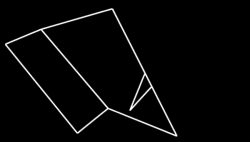
Some of the edges on the missile fins will vanish at certain view angles. The explanation for this is simple. Edges are considered visible if both vertices are visible, and at least one of the two associated faces is visible. If you look at the edge at the bottom of each fin, it sticks out diagonally from the missile, and should be visible if either of the two adjacent sides is visible or the bottom is visible -- but we can only pick two. So the edge is linked to the missile's bottom face and one of the two sides. If the missile is pointed toward you (raise shields!), the edge will be visible or not depending on the missile's rotation.
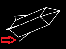
The problem could have been reduced by putting the fins in the middles of the sides, rather than at the corners.
The triangular windows on the front of the shuttle disappear at the wrong time. The edges are tied to faces 10 and 11, which is correct. The vertex faces are a bit scattered though. For example, vertex 13 is only visible if faces 0 or 2 are visible, both of which are facing toward -X. If you spin about the Y axis, at certain angles the starboard window disappears when facing straight at the viewer. Similarly, 4 of the 6 edges are not visible in the top view.
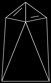
The vertex face data for the windows looks almost random. Like the edges, they should only depend on faces 10 and 11. These problems do not occur if the vertex visibility test is disabled in the visualizer. (Vertex visibility testing does not appear to be required for correctness on any of the meshes, so it can safely be disabled in the visualizer.)
On a different note, the window edges have independent LOD distances. At distance 5 you see all three edges in each triangle, so at distance 6 you see two edges, at 8 you see only one, and at 9 they vanish entirely. This looks strange at high resolution but makes sense for low-resolution displays.
Some views are correct, some views are completely wrong, for a simple reason: the offset to the list of faces is bad. The face data points into the header for the Shuttle. It happens to work well enough not to cause a total failure.
The vertex and edge data is fine, so if we fix the surface normals it renders correctly.
Not a bug, just an oddity: the Thargoid and Thargon meshes are defined sideways (90 degrees about Z) to how a "flying saucer" would be expected to look. This means that when they climb or dive it looks like a rotation of the ship rather than a change in angle [assuming there's no special treatment in the code].
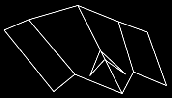
Found in the C64 version, the Cougar stealth ship is decidedly non-convex, with edges that confuse the surface-normal correction algorithm. Fortunately the original surface normals work fine, so we can just turn correction off.
Copyright 2020 by Andy McFadden