October 16, 1997
by cfh@provide.net
Click here for a 6k ZIP file of the Tempest Tubes ROM image needed for the following hack.
Note the combination ROM files were created by concatenating the original ROM files using the following MSDOS copy command with the "/b" parameter:
copy /b rom1+rom2+rom3+rom4+rom5 allroms
Assumptions:
- I am assuming you know how to solder. And I'm assuming you have a
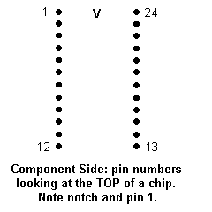
general idea of chip orientation in regards to pin numbers. For example,
here are how chip pins are numbered:

Making Tempest Have Switchable Tubes (cylinders).
Duncan Brown created a version of Tempest with new shapes called "Tempest Tubes". Identical to the original Tempest, just completely different tube (cylinder) shapes (game is much harder). This is a single chip change. You just plug in the new 2716 or 2516 at position 118 (also known as "K1" and "ROM4") on the logic board.
I like the new version. But I would also like to be able to switch between the original and new Tempest Tubes without pulling chips. This explains how to do that. (If you want just the 2716 version of Tempest Tubes with NO switch, just burn the file TTUBE118.716 into a 2716 instead of doing the following steps).
Note: this mod only works with the 12 ROM version of Tempest, where all ROMs are 2716's or 2516's. I guess there are some 6 ROM versions Tempest boards using 2732 EPROMs, where this procedure and ROM files will not work.
What you need:
- a 2732 EPROM
- the TTUBE118.732 file
- access to an EPROM programmer
- a soldering iron
- a small SPDT two position switch (NOTE: choose one that does not require much force to change position)
- hot melt gun or silicon sealer.
Procedure:
- Burn the file TTUBE118.732 into a 2732 EPROM. Obviously you'll need an EPROM burner for this chore.
- Bend up pin 21 of the 2732 EPROM (so it can NOT be inserted into a socket), and solder a small one inch long wire to this leg. Solder the other end of this wire to the middle contact of the small SPDT switch.
- Solder a one inch long wire to pin 24 (+5 volts) of the 2732 EPROM. Be careful not to get the leg all covered in solder as it still has to be inserted into a socket. Solder the other end of the wire to one of the remaining lugs on the switch (doesn't matter which one).
- Solder a one inch long wire to pin 12 (ground) of the 2732 EPROM. Again, be careful not to get the leg all covered in solder as it still has to be inserted into a socket. Solder the other end of the wire to the last remaining lug of the switch.
- Using a hot melt gun or some silicon sealer, glue the switch to the top of the 2732 EPROM directly over the quartz window. I recommend using the hot melt glue gun method. Important: position the lever on the switch towards the notch (pin 1 and pin 24) on the 2732. If you don't do this the chip may not fit in the logic board, and using the switch will be difficult. If there is too much force required to "flip" the switch, it may cause damage to the socket on the board.
- Remove the original 2716 or 2516 EPROM from the Tempest logic board at position 118 (also known as "K1" and "ROM4"). Insert the 2732 into this socket with the notch in the same position.
Now you can open the coin door and change the switch anytime you want. You can even do the change while the game is powered on and running.
2732 Reference Diagram (as viewed from the top of the EPROM):
              (notch)
        ++++++++\  /+++++++
       1|        \/  /----| 24 (+5)
       2|    \       |    | 23
       3|     \      |    | 22
       4|    __\__   | /--| 21 (A11) <-- leg bent out of socket.
       5|   |     |  | |  | 20
       6|   | SPDT|  | |  | 19
       7|   |_____|  | |  | 18
       8|    | | |___| |  | 17
       9|    | |       |  | 16
      10|    | |_______|  | 15
      11|    |            | 14
(GND) 12|----/            | 13
        +++++++++++++++++++
How It Works:
The 2732 EPROM contains both the original version of Tempest, and the new Tempest Tubes. Moving the switch enables or disables the highest address line (A11) on the 2732; this cuts the 2732 into two halves, with only one or the other half enabled at a time. So when the switch grounds pin 21, the first half of the chip (original Tempest) is used. When the switch ties pin 21 to +5, the second half (Tempest Tubes) is used.
Making Sure It Works
You can immediately notice the difference in the cylinder (tube) shapes when you press the player one switch, and you are prompted to choose the starting game level. If you move the switch during this time, you can immediately see the different tube shapes shown in miniature on the screen.
Good Luck!