|
Because there was some interest in my last post with the pretty
pics, I thought I would do it again. This time I am going
to explain some of the new modules I created. This will allow
you to plug in the schematic values and out comes the proper
result. I won't go in to the actual code details because that
is all explained in the source code. The source code will
be available on the compile board when I get around to posting
it.
I hope to create all my new modules this way. All the work
is done by the code now, instead of me measuring and breadboarding
circuits. The modules are tested against breadboarding and
spice simulations to confirm accuracy. So lets get started.
I will explain parts of the Pool Shark score sound. When you
make a shot the game makes a tone that increases in frequency.
If you make a few shots in a row, each gets higher in pitch.
When your streak ends the tone starts at the beginning again.
This is all done with discrete components. The micro only
sends a trigger saying a score has been made. Here is the
schematic of the sound effect.
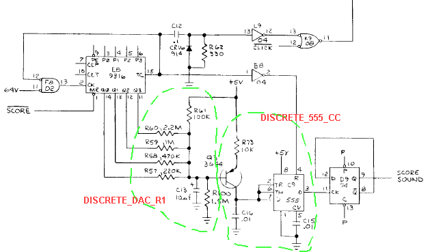
I will skip over explaing the counter and other circuits not
highlighted. The new discrete modules are in the dashed lines.
Let's start with DISCRETE_DAC_R1.
This whole circuit creates a voltage that drives the base
of the transistor. This voltage determines the frequency outputted
from the DISCRETE_555_CC module. The counter (E8) outputs
a binary value from 0-15 when triggered then rests at 15.
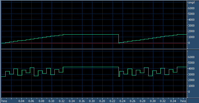
When the power is first turned on the counter will also cycle
once because it was not at 15. If we remove capacitor C13,
we can see the voltage pattern created by the counter in the
bottom waveform in the following pic. The top waveform is
just to show the count in a *100 scale for reference. The
bottom waveform is in millivolts.
With C13 back in, it causes the voltage to not change as rapidally.
Also it will take about 4s when first powered up to get to
the resting voltage. The lower the voltage the higher the
frequency. As stated before, a score sound is triggered at
power up. The frequency on the real board may be too high
to hear, but because we have a 11kHz-48kHz sample rate to
deal with, an alaised frequency comes out. So the intial power
up sound may sound different then the real board. It can't
be helped unless we sample at 96kHz+.
This pic shows the voltage (mV) created at the base of the
transistor as capacitor C13 charges.

.
So after the 4s startup, and we start playing the game, hopefully
a ball will go in and a score will get triggered. This causes
the voltage to drop. The more scores that get triggered close
together, the more the voltage will drop. This is seen in
the following pic. The top waveform is just to show the count
in a *100 scale. The bottom waveform is in mV.
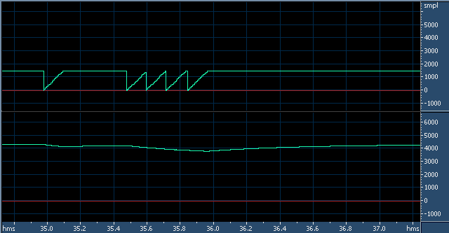
Here is a closeup of the voltage created by the DISCRETE_DAC_R1.
Notice that the voltage drops after the first score, starts
to raise but then drops again as the other 4 scores get trigger.

Here is a single score with no other score happening. Remember,
the downward slope is when the counter is running. Then the
voltage slowly returns to its resting state.

So now we have an accurate voltage to feed to the base of
the transistor of the DISCRETE_555_CC module. This module
emulates a 555 timer being charged from a constant current
source. Basically this means the 555 circuit as shown is a
VCO (voltage controlled oscillator.)
This circuit generates quick negative going pulses like the
real thing. This is usually sent to a counter. In the score
effect, it is /2. Also because of the way a 555 timer works
after a reset, you will notice the first pulse is wider then
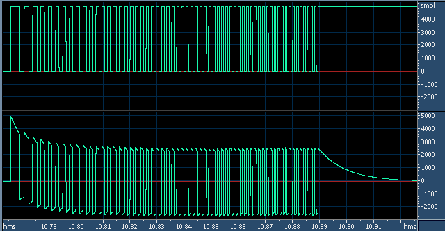
the rest. So here is the DISCRETE_555_CC output at the top
and then being /2 to make the actual score sound at the bottom.
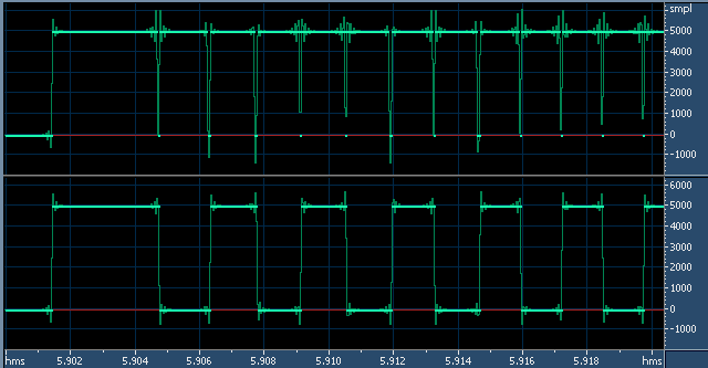
This is what we end up with after all is said and done. The
top waveform is the output of a single score sound after the
/2 stage. But notice the DC at the end. So we send it through
a high pass filter like the original PCB and end up with the
completed bottom waveform.
Now if you are still awake, I will sum it all up.
The modules automagikally work out everything from the schematic
values. Every component in the dashed lines are entered into
a table to be used by the module.
These circuits are used in a lot of games. No work other then
typing in the values is needed any more. These modules contain
a lot of options to cover various cases. Such as when I removed
C13 from the DISCRETE_DAC_R1 to show the waveform earlier.
If I had chosen to do a more basic emulation, we would end
up with score sounds that all sound the same. As heard in
the current 78u6 driver.
I will be doing more modules in this fashion. It makes game
driver coding easier. And you can see a direct link to the
schematic when trying to figure out how it is all done. Of
course making these new modules is a pain, and each requires
testing to ensure accuracy in all cases.
As for the question of speed hit... this will actually make
some games faster because of reduced node count and no longer
using multiple slow waveform generators.
Hopefully this shows where the discrete coding is heading.
Please do not ask which games will use this code. All I can
say is most of what I have already done uses some of this
and a lot of future games too. So now I have to redo my old
drivers.
Goodnight and have a pleasant tommorow.
D.
|