mirrored from http://stickycarpet.com/pinx/cc.html
How to convert
|
|
 |
|
to Jamma
![]()
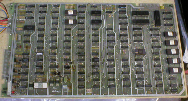
One of my all time
favourite games is Crystal Castles by Atari.
As i couldnt afford a dedicated cabinet (Update), i decided
to go for a pcb and convert it to play in one of my Jamma cabs.
This isnt as easy as it sounds, so i thought i would put a page on my site
showing how i did it.
The following notes are for reference only and although
i am happy for anybody to use them,
i will not be held responcible for any mistakes/damage done to your pcb's
or cabinets !!
![]()
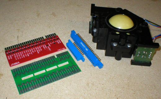
Things you will
need.
You will need the following parts to be able to convert
a Crystal castles pcb to Jamma :
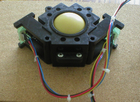
1) A trackball, preferably an Atari one and one that will fit in your Jamma control panel.
2) An Atari Crystal Castles pcb
3) A 28 way Jamma finger board.
4) Bundles of different coloured wire (
black, red, green, blue, orange, yellow and regular twin core speaker wire)
5) Edge connectors, a 2 x 10 way and a 2
x 22 way.
6) Solder.
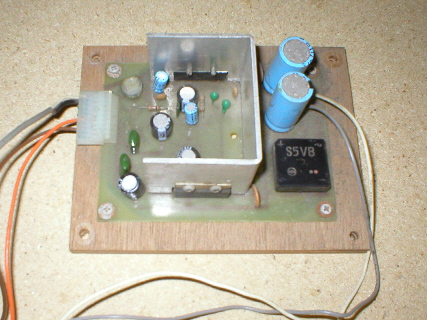
7) A small 12v Amp.
 |
|
|
 |
![]()
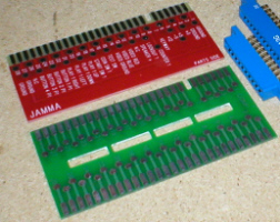 |
Where to start ?
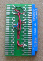
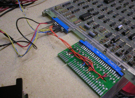
Well i like to start with the Adapter itself first. As you can see i have 2 different types of finger board available to me (pic on left), which means i can make 2 different styles of adapter, but they both do the same job. Looking at the pic on right, you will see that using the red single sided type of finger board, gives you a loose flexible wire type set up, or using the green double sided type gives you a neat and compact set up. For making the Crystal Castles adapter i am going to use the green compact style set up. |
 |
![]()
 |
Edge connector 1.
Taking the 2 x 22 way edge con (available here) you will need to add elongated blobs of solder to all the pins on both sides pic on left, then take the green finger board (available here) and add elongated blobs of solder to the strips along the edge on both sides. This is the edge without the keyway / notch. pic on right. |
 |
![]()
 |
Edge connector 1 cont..
Once you have added all the solder blobs, slide the green finger board down the middle of the edge connector between the pins and line the pins up with the strips so that you are almost central, you should have 3 strips too many one end and 2 strips too many the other end on the finger board, now using a flat bladed screwdriver press each pin down onto the strip underneath it and reheat the solder with the iron and let it cool to form a joint pic on left. Once you have soldered all the pins the finger board should be solidly connected the the edge connector pic on right. |
 |
![]()
|
Part side. |
Pcb pinouts.
Now that we have the basis for an adapter we need to add the relative wires for the game power, colours, sound and controls. These are known as the game board pcb pinouts, here i have listed the large connector pinouts*, part side (or component) and solder side. I have taken these straight from the Atari manual for this game. Pinouts are available for other games inc Crystal Castles here : www.spies.com/~arcade Some of the pinouts on the pcb we will not need to use as these relate to Atari's ARII audio regulator pcb and concern sensing circuits. Also the pcb uses a 10.3v+ but as its very close to 12v+ we can get away with using the 12v+ from a Jamma p.s.u. for this purpose. Careful attention MUST be taken when making the conversion from pinout info to actual wire link, as numbers and letters are used for correspondance and in some cases certain numbers and letters are not used as they could look too much like one another (i.e. a G and a 6) Using the standard Jamma pinout below make the corresponding links from Crystal Castels to Jamma. * The small connector pin outs will be dealt with in page 2 . |
Solder side. |
![]()
|
Standard Jamma pinout.
We will not be using all the pinouts, just the ones in Red. Do not bother making the links for sound yet, as this will be dealt with in page 2. |
|
Part Side (Comp). Ground (gnd) 1 |
Solder side. A
Ground (gnd) |
|
Key for wire colours. This is the Key that i like to use for the wires on the adapter : Black = for all Grounds (GND) inc video Ground. |
![]()
 |
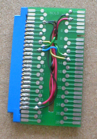
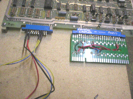
Adapter after basic connections.
So, after making the basic connections, you should have an adapter that looks something like this. Pic on left is parts (comp) side and Pic on right is solder side. Now we have the controls and speaker connections to make, these will invovle the second small 2 x 10 way edge connector, the track ball and the amplifier for the sound. At this point, i get a paint pen and write on the edge con what game it is for and i also write parts on the part side and solder on the solder side. This way at a glance you know what its for and which way to put in on the pcb. |
 |
![]()
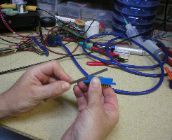 |
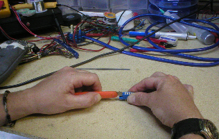
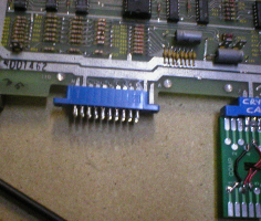
Small edge connector.
The small edge connection on the Crystal Castles pcb is a 2 x 12 way, but these i could not find anywhere, so i got a 2 x 10 way one instead and modified it to fit, as luckily, we dont use all the pins on the small connector. I used a 1mm thick needle file and a disposable stanely knife, to create a slot in the end of the edge connector. I started by filing first (pic on left) untill i got down to a point where i would of started to rub against the pins inside. Once i got to this point i used the knife to cut little nicks out, untill i was flush with the bottom of the ledge (pic on right). |
 |
![]()
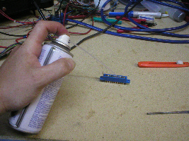 |
Small edge connector cont...
Once i had done this i gave the whole connector a good blow out with an air duster (can of compressed air). Then i lined the edge connector up with pin N on the edge connection (1st pin on left, see pic on right) so that pin A and B hung out of the right hand end of the connector through the slot i had filed / cut earlier, it was then a matter of pushing it on, so that it sat in place. Now is a good time to get a paint pen and right part side on this con too. |
 |
![]()
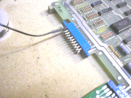 |
Small
edge connector wiring. |
 |
![]()
 |
|
![]()
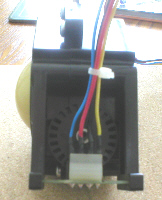 |
Optical
wheels and loom connectors. Now turning
the enclosure on its other side (so the left encoding
wheel is facing you) i again number these pins from left to
right :
1, 2, 3, 4 . So this is the Left hand
connector and the wiring for this is as follows : |
 |
![]()