Hardware and Software Information
Assault had some ground breaking hardware and software for it's day. It featured a technology called "growth motion object hardware", which was responsible for the great scaling and rotational effects in the game. It also has full-fledged FM synthesis of sound effects and background music. Sadly, Assault wasn't as impressive as it could have been. There are quite a few features that weren't finished. Let me tell you about them....
The board is Namco System 2 with a JAMMA connector. There are two other connectors on the board - both unused. The schematics on the manual offer some hints as to what these connectors were designed for.
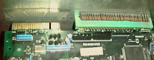 Unused 48-Pin Edge Card, next
to the JAMMA connector. (see manual, p5-29) Note that this card
edge isn't connected to the backplane. If you want to use it,
you'll need to open up the metal cage to get directly to the PCB.
Unused 48-Pin Edge Card, next
to the JAMMA connector. (see manual, p5-29) Note that this card
edge isn't connected to the backplane. If you want to use it,
you'll need to open up the metal cage to get directly to the PCB.
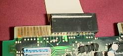 This connector
outputs Stereo sound! It just so happens the
that sound connector uses the same pin widths as IBM PC
connectors. I used an old MFM drive cable, but a floppy cable
would have worked too. It's small enough to fit between the PCB
and the backplane. Since the cable's connector was too small, I
cut one end open with a Dremmel tool. I can get away with that
since all the pins I care about are on that one side. It is
possible to connect this wrong- be carefull!
This connector
outputs Stereo sound! It just so happens the
that sound connector uses the same pin widths as IBM PC
connectors. I used an old MFM drive cable, but a floppy cable
would have worked too. It's small enough to fit between the PCB
and the backplane. Since the cable's connector was too small, I
cut one end open with a Dremmel tool. I can get away with that
since all the pins I care about are on that one side. It is
possible to connect this wrong- be carefull!
Once you've wired up the headphone connections (see chart
below), you can test the left/right orientation with the system's
test mode. Play the FM sound #20- it will play a sound on left
and then the right channel. Note that the volume control knob
behind the coin door only affects the mono speaker. The headphone
connections aren't affected.
| Pin | Label | Description |
| A1 | SPR+ | Mono speaker + |
| B1 | SPR- | Mono speaker - |
| A2 | PHR | Headphone right |
| B2 | PHL | Headphone left |
| A3 | 3DL | 3D sound left |
| B3 | AGND | Analog ground (for headphones) |
| A4 | 3DR | 3D sound right |
| B4 | 3DCOM | 3D sound common (not a ground!) |
| A5 | -key- | |
| B5 | -key- | |
| A6 | GOUT(0) | CPU connection. Possibly shutter glasses?? |
| B6 | GOUT(1) | |
| A7 | GOUT(2) | |
| B7 | GOUT(3) | |
| A8 | GOUT(4) | |
| B8 | n/a | |
| A9 | VCC | +5v |
| B9 | GND | Ground |
| A10 | VCC | +5v |
| B10 | GND | Ground |
| A11 | n/a | |
| B11 | <<RINGOUT | CPU connection. Possibly shutter glasses |
| A12 | >>RINGINK | or network connection?? |
| B12 | >>RINGINA | |
| A13 | <<RINGSW | |
| B13 | <<SCOUT | |
| A14 | >>SCINK | |
| B14 | >>SCINA | |
| A15 | ?? | Connection to an IO chip?? |
| B15 | ?? | |
| A16 | ?? | |
| B16 | ?? | |
| A17 | VCC | +5v |
| B17 | GND | Ground |
| A18 | VCC | +5v |
| B18 | GND | Ground |
| A19 | AN(0) | Unknown connection. Possibly the |
| B19 | AN(1) | network connection??? |
| A20 | AN(2) | |
| B20 | AN(3) | |
| A21 | AN(4) | |
| B21 | AN(5) | |
| A22 | AN(6) | |
| B22 | AN(7) | |
| A23 | <<ADVCC | ?? |
| B23 | <<ADGND | ?? |
| A24 | <<ADVCC | ?? |
| B24 | <<ADGND | ?? |
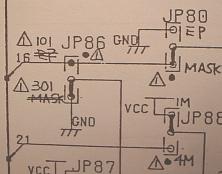
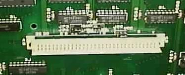 Unused 62 pin DIN connector
on the bottom center of the PCB. (see manual p5-45). This
connector goes straight to the "OBJ ROM" set of ROM
chips. There are some near by jumpers, one of which directly
powers off the built-in ROMs. My guess is that this connector is
an expansion port for new levels. Plug in a card with some ROMs,
move a few jumpers, and wa-la! You have a whole new game! I'm not
skilled enough to create a new add-on card, but it does appear
that it's functional.
Unused 62 pin DIN connector
on the bottom center of the PCB. (see manual p5-45). This
connector goes straight to the "OBJ ROM" set of ROM
chips. There are some near by jumpers, one of which directly
powers off the built-in ROMs. My guess is that this connector is
an expansion port for new levels. Plug in a card with some ROMs,
move a few jumpers, and wa-la! You have a whole new game! I'm not
skilled enough to create a new add-on card, but it does appear
that it's functional.
Features shown in the game's "Test Mode", but not fully implemented:
Signs of a product rushed to market:
Manual misprints
Other Interesting Notes.
Other Technical specs
(attach sound and music hardware information here)
![]() Back to the main page
Back to the main page