| This is a series regulator with Q900 being the control element, Q901 a driver, and Q902 an error amp. ZD900 forms the emitter reference voltage source. Since the generated high voltage and other voltages are linked by means of the magnetic field of T900, any change in H.V. will be reflected back to all of the other voltages. This H.V. fluctuation is sensed on the 90V line and is used to control Q902. R906 and R914 are used to limit the range of H.V. adjustment by R905 to roughly 13.5 to 15.5 KV @ 0 beam current. ZD901 and C905 provide a means of dropping a large DC component without attentuating the error voltage that is needed to stabilize H.V. line. R904 provides a means of biasing ZD900 to insure a stable reference voltage for the error amp to work against. R902 and R903 is the collector load resistor for Q902 and biases Q900 and Q901 in the absence of an error signal. | The error amp. Q902, can only divert some
of the base current from Q901 and shut the regulator down. It can not
increase the conduction of the regulator above a level determined primarily
by R902 and R903 and the current gain of Q900 and Q901. R901 is a buffer
resistor to protect Q901. C903 and C902 are used to suppress any tendency for high frequency oscillation that could generate radio frequency interference. C900, C901, C904 and R911 are filters and damper to minimize ripple on power lines as well as to decouple 25 KHz pulses that are impressed onto the + 38V line by a normally operating H.V. generator and prevent interference with other circuitry. L901 is a small high frequency filter choke to decouple the H.V. generator from the +VE supply rail and minimize line conducted radiation. |
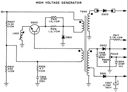
| Q903, R907, R910, C906 and T900 form a free
running Hartley Oscillator circuit that operates at approximately 25
KHz. The operating frequency is primarily determined by transformer
and transistor characteristics. Feedback is established by the proper
phasing of primary to feedback winding. AC feedback is determined by
the turns ratio of primary to feedback winding as well as R908 and C906.
The transistor must also be forward biased sufficiently to where oscillation
can start when power is applied. This is controlled by R907 and R910.
L900 is not essential to circuit operation but helps smooth out the
AC waveform generated into a reasonable approximation of a sine wave.
R915 and R916 are Safety resistors that |
will burn out, and prevent damage to Q903,
should the output circuitry come under excessive current drain. D900 is a surge diode. There are two secondary windings. The H.V. winding delivers sufficient AC to the H.V. rectifier D903 to generate 14.5 KV anode voltage at a maximum current of 100 ua, and tapped lower voltage winding that is used to generate focus voltage of 0 to 410 VDC, and G2 voltage of + 410 VDC, and + 90 volts for operation of the 2 amp circuitry. D900, 901 and 902 are fast recovery diodes to operate @ high frequency of 25 KHz. |