![]()

![]()
![]()

![]()
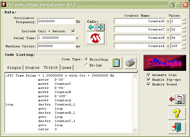
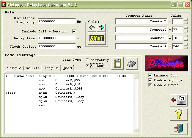
For you PIC & Scenix-SX microcontroller programmers, I've made a pretty nice little delay loop calculator for Windows.
PicLoops includes support for Microchip PIC chips and the Scenix SX chips running in Turbo mode. PicLoops is free but I reserve all rights as the creator.
PicLoops makes figuring out the values for delay routines a snap and it is incredibly easy to use. You won't even have to type the assembler code for the routines because it does that for you too. Transferring the code to your own program editor is a simple copy & paste operation.
Notice: The "?" button within PicLoops opens the user's manual file "PicLoops_v2_2.pdf" in the system's default pdf viewer. Typically that is Acrobat Reader so that program would also have to be installed on your system if you want to be able to view the file.
PicLoops v2.2 is available here. Download this exe file: PicLoops_v2_2_Setup.exe (5.1 MB) Last updated Jan. 9, 2008
After downloading the exe file to a temporary folder, double-click it to launch the installation of PicLoops.
Microchip mode (PIC & Scenix Compatible):

Scenix Turbo Mode:

Do I need PicLoops?
Granted the PicLoops program is getting a bit old, but it is still very useful if you are writing your programs in assembler. These days, with so many high level language compilers available for PICmicro's, fewer and fewer people are programming in assembler so PicLoops is becoming somewhat obsolete. Most high level languages include statements such as "Pause (n)" or "Delay_ms(n)" that automatically provide exactly the same function and generate exactly the same assembler code as PicLoops does. The bottom line is that if you are using a high level language compiler, you will not need PicLoops.
I usually write my programs in C nowadays so I rarely use PicLoops anymore. However, it is good for all people who plan to spend a lot of time programming PICmicro's over the long term to understand in detail exactly how a PICmicro works. To accomplish this, learning assembly language programming is key. When you enter the world of assembler, you will invariably run into situations where you'll have to write your own delay loop routines. This is where PicLoops becomes a valuable tool. To the experienced programmer, PicLoops instantly performs the mundane repetitive calculations and provides the copy & paste tool so you can create your code and drop it into your target program quickly. For those who want to learn about the delay loop structure, PicLoops provides a standard code structure to start with, thus preventing people from guessing and thus writing bad code and thereby forming bad habits that can follow them for years or even for the rest of their careers as programmers. PicLoops also demonstrates how loops can be nested within other loops to create longer delay periods. The PicLoops documentation even provides the calculation formulae. From this perspective, PicLoops is a learning tool.
Where did PicLoops come from?
I wrote the first version in DOS QuickBasic in 1994 to serve as a tool for myself because I was pulling out the calculator several times every day to figure out the delay loop starting values manually. Later I wanted to learn Visual Basic programming and PicLoops was a sensible project to start with. It worked out pretty well so I decided to provide it online for anyone who might find it useful. I know that it has been used in several classrooms in high schools and colleges and by hobbyists and engineers too.
What about creating similar tools for timers and interrupts?
There have been times over the years when I've seriously considered writing more features into PicLoops to add the ability to generate code for timers and interrupts. Several people have written and suggested it. I even started writing code for it more than once. The problem that came up is that there are literally hundreds of different PICmicro devices to choose from. A standard delay loop is universal among PIC's, but timers and interrupts are not. The 16x5x series has no interrupts so timer code is easy. Other PIC's have 1, 2, or 3 timers and some have even more. Some timers are 8 bit and some are 16 and some can be configured as either. Timers can run free or they can control other peripherals such as timer 2 working with the CCP module. Then there are the prescalers to consider. Timers can be used with interrupts or without and they can be shared by many functions within the same program. As you can now imagine, it would be difficult to account for every possibility in every PIC. Regarding interrupts, there's a similar problem. The 16x5x series has no interrupts but other PIC's have many. What really complicates matters the most is that the data memory banks are laid out differently across PIC families and even within the same family in some cases. That means that writing assembler code that will perform the most important function of any ISR (interrupt service routine), that of context save and restore, is very different depending on what the memory architecture is like within a specific PICmicro. For any timing function to be accurate, one must take into account the number of clock cycles used by every line of code, including those used by the timer ISR and even those used by other ISR's in the event that they cause the timer ISR to be delayed. As I tried to create a new Windows application to do all of this stuff, it very quickly became apparent that the forms were becoming very complex and the amount of code that I would have to write would have amounted to a full time job for about a year and I knew I could not dedicate that much time to the project. PicLoops is a relatively simple tool and as such it is easy to learn and to use and so beginners to PIC programming find it friendly. I didn't want to create a complex and scary application that beginners would find initially confusing and frustrating. I guess that's the real trick however when creating such an application, finding that perfect balance of function and ease-of-use.