 |
 |
All of the pictures can be viewed in high resolution, by clicking on the image.
The CPU Stack
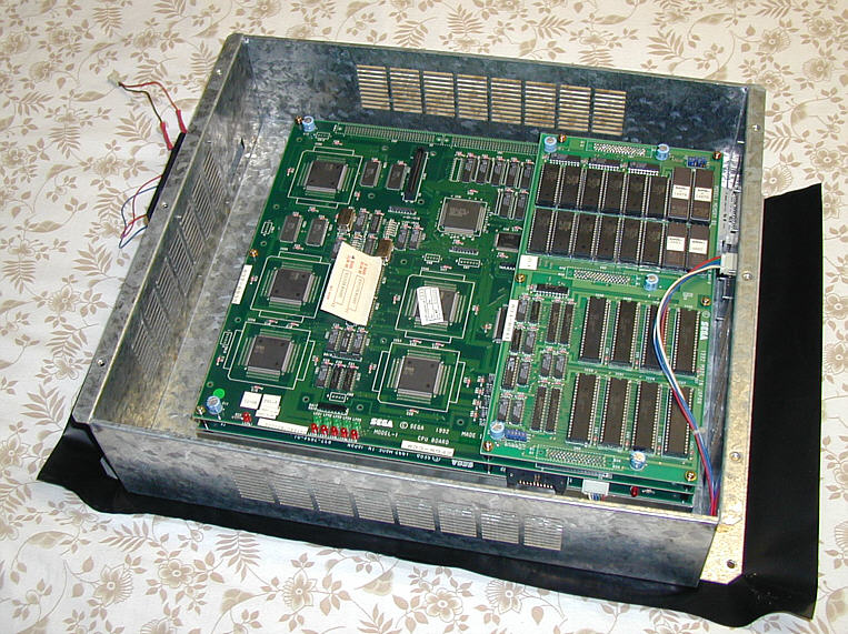 |
This is the main CPU stack, inside it's metal shield case. It comprises the boards below, which sit one on top of another, and form the main processing center of the system. This stack does not perform any of the input/output functions, such as controlling the force-feedback, reading the steering, accelerator and brake, and flashing the lamps. It communicates it's intentions via a two-way serial link to an I/O board. |
 |
This is the CPU board, which centers around an NEC V60 16MHz processor. Although it's only 16MHz, it is supported by Sega Floating point processors, of which there are five on this board. |
 |
This is the Video output board. It contains all the memory for the display, which is output at High-resolution EGA standard, which is known in the Arcade industry as "medium resolution". The horizontal scanning frequency is 25KHz, as opposed to 31.5KHz for VGA. |
 |
This is the communications board. It has it's own separate Z80 processor to control the multi-way communications with the other CPU stack in the twin, along with any other machines it is connected to, and the Live commentary monitor. It communicates using two fiber-optic cables, one for Transmit, the other for Receive. They are connected in a ring to the other boards - E.G. 1tx connects to 2rx, 2tx connects to 3rx, 3tx connects to 1rx. |
 |
This is the memory board, although a more proper name for it would be "program board". IT contains the roms which house all the game data. Note that the sound data is not on this board, but on a separate sound card. |
It's a tribute to technological advance when you consider that in just nine years, one mediocre graphics chip out of your PC has the power of ten of these stacks of PCB's! The latest 3D graphics chips can render approximately 1,000 times more polygons per second than one of these stacks of PCBs!!
Other Cards
| This is the main sound card, and contains the sounds of the game in ROM. It contains it's own processor, a 16 bit Motorola 68000. This controls custom Sega sound chips. Control data is passed to and from the CPU stack via a bi-directional serial link. |  |
| Here is the sound option board, which usually sits on top of the main sound board. It contains an extra ROM, and I believe it is used to allow more sounds to be played at once. The output of this and the main card are fed to a small mixer card, before being passes to the stereo amplifier. |  |
| This is the I/O card. It talks to the CPU stack via a two way serial link. This is the card that controls all the lamps, as well as sensing the steering, gear shifts, VR buttons, start switch and coin inputs. It controls lamps up to 6v directly, but uses solid-state relays to control the 110v lamps. This normally sits in a metal shield housing, similar to that used by the CPU stack. This board also has a fiber-optic communications port, but it is not used in Virtua Racing. |  |
| This is the audio amplifier. It also acts as a 12 volt power supply for the CPU stack fan. | PIC? |
Other Components
 |
This is the wiring loom for the rear cabinet. When I first saw this, I wondered just how on Earth did you need so many wires to play a game?! Now I can see just what's involved with all those PCBs talking to each other! |
 |
Here is the wiring loom, re-assembled back into the now cleaned rear seat unit. There is a stain of some sort of drink on the right hand side. This had seized up one of the fans which is meant to blow cool air from the rear to the front (top to bottom in the picture). How someone didn't get blown up when this happened is beyond me (maybe they did!), because the fan is 240 volt. Luckily, it missed the other circuits that sit there, the Power supply and the amplifier for player one. |
 |
This is the rear view of one of the force-feedback steering assemblies. On the left you can see the bi-directional 100 volt AC motor, which produces some serious pull when set to maximum. There are two VRs, one for the game, which is read by the I/O board, and one for the Force feedback control board, which sends it data back to the CPU stack via an 8 bit parallel interface to the I/O card. |
end of page