
The Breadboard Pokey Project
The Atari Pokey chip, pictured above is used on several of their early 8 bit computers, but is used much more widely in the early 80s video game PCBs, where it produced much of the sound effects and music for the games.
I've always been fascinated by the internal workings of customs chips, including this one, and recently I obtained a technical description and schematic for the internals of the Pokey, so I decided to see if I could make one! These chips are reasonably plentiful at the moment, if you know where to look, but in the future will slowly become harder to find, and so a replacement will be needed. Hopefully, this project will allow a suitable, affordable, and above all, compact replacement to be made.
The Technical data for the Pokey can be downloaded in a .pdf file here
I was undecided about which route to take. The pokey has already been emulated for MAME, and so the source code to a pokey emulator was already available. This could be re-written for a fast microcontroller, and with a few additional chips, could be made into a Pokey.
However, my machine code is not anywhere near up to what would be required for that, but I do know my way around a logic circuit, so I decided to re-create the main functions of the pokey using simple logic, and some GALs.
The idea is to build one first, using only GALs for the address decoding and simple tasks. Then, when a complete working schematic was available, stat reducing the chip count by using CPLDs for more and more of the functions, until hopefully, it could be fitted into a couple of chips and some discreets.
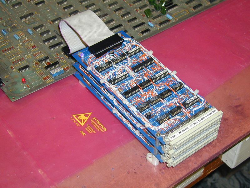
So, here it is, my first Pokey on a breadboard! You can click on any of these photos for a larger view.
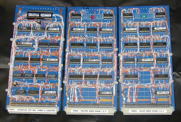

Quite a few components there, on three PCBs! And not all of the functions have been re-created. The working functions so far are:
1. Random Number Generator, including all Polynomial counters
2. POT input - in digital mode only, but it does emulate a 1 bit ADC for each
channel in analog mode
3. All 4 audio channels
functions not currently implemented are:
1. Serial interface
2. IRQ Register
3. Timer function
4. High pass filters
5. Keyboard scanner
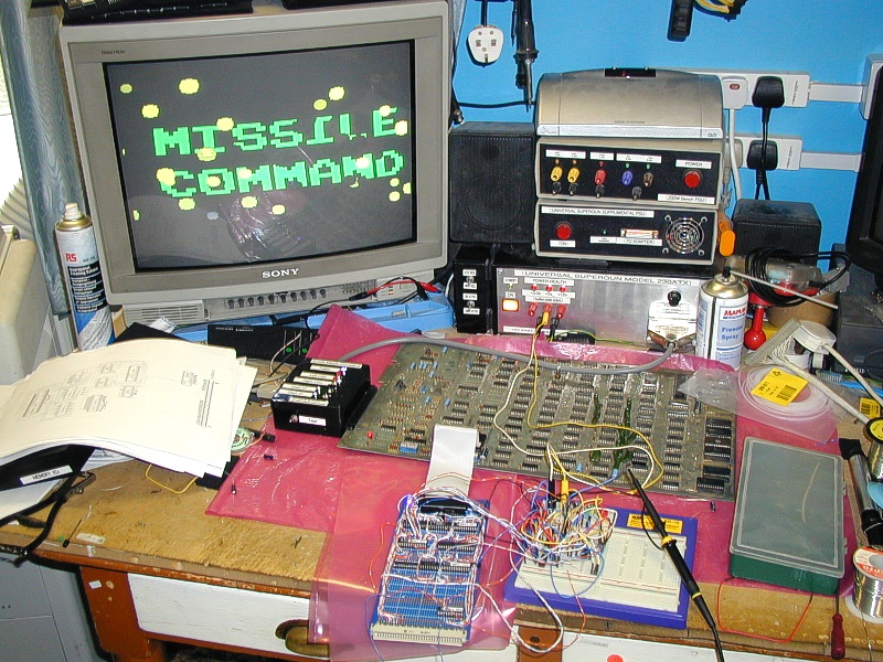
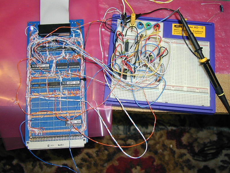
Here's some photos of the initial work in progress. I'm using a Missile command PCB as my primary test bed, as it is simple to run a game, and check that the sounds coming from it are what they are supposed to sound like. Also, MC uses the random number generator, and pot inputs, so these are easily tested.
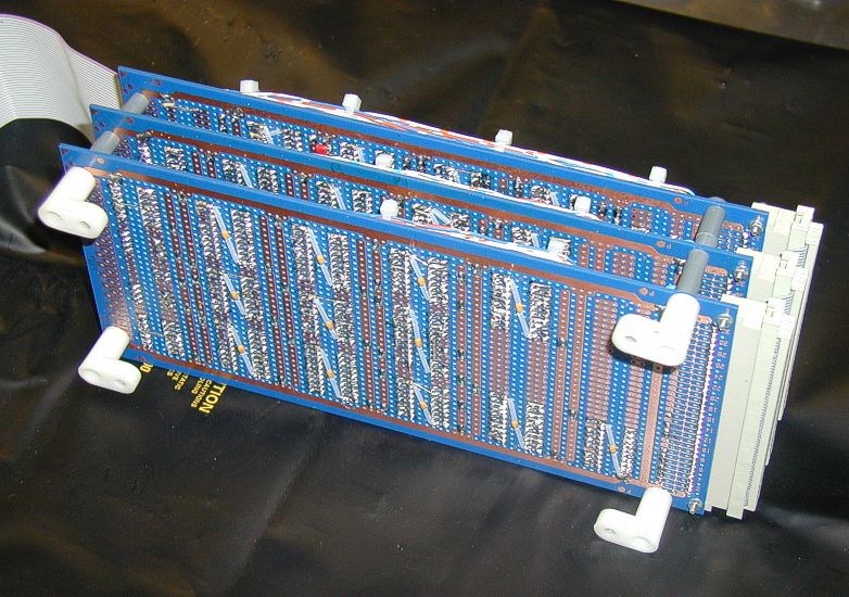
This master-card has a 64 way DIN connector on the end, with some of the bus signals routed to it. This is to allow other DIN cards to be plugged into it via a mother-ribbon cable, to complete the functions.
Here is the completed 3 PCB stack running on the Missile Command PCB.
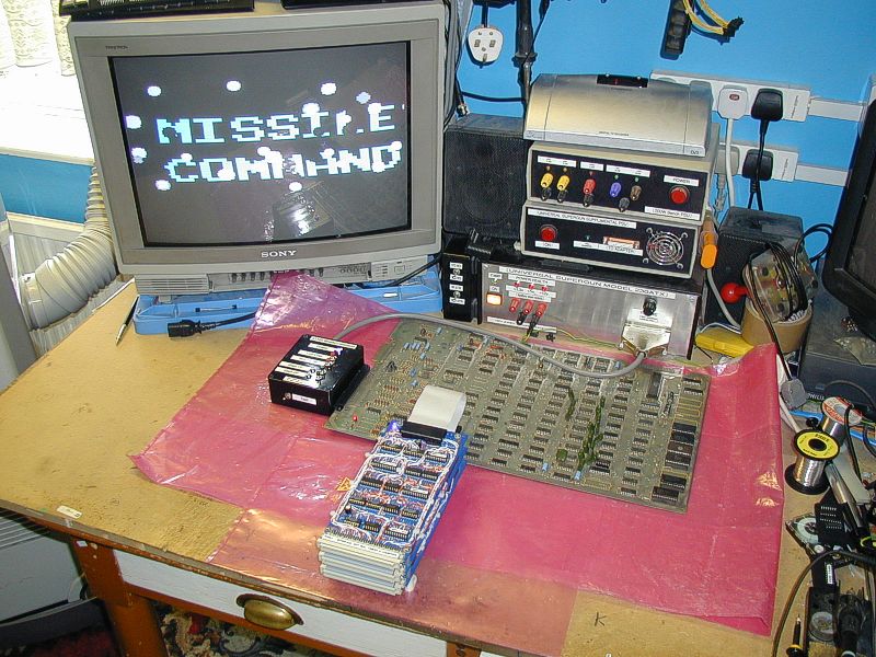
It works very well, better than I anticipated. I've got a few teething problems, like some random firing of the audio channels when it's first powered up, but I think that's just noise induced by crosstalk on the wiring - it goes away after about 20 seconds. I had problems with the shift registers for the Polynomial counters locking up as well, but using 74F164s instead of 74LS164s seems to have cured that. The only ongoing problem I have is the volume - it's very low compared to a normal Pokey. I've spec'd the outputs as it says in the Pokey tech document, but it's still very quiet! I'm sure I'll get it sorted eventually.
I've published the schematics for the 3 PCBs in .pdf form in the following links:
PCB1 - Interface, POT register, timers
and counters
PCB2 - Master audio card, channels 1 & 2
PCB3 - Slave audio card, channels 3 & 4
Also, between the 3 PCBs, there are 8 different GALs, the sourcecode and JEDs for them are here.
If you fancy building one of these yourself, please let me know how you get on! Soon I'll sit down and try to go to stage 2, of maybe making each PCB run with just 1 or 2 CPLDs and some support, but I'm going to take a long break from it before that happens!!