By Jed Margolin
In this geometric model there is an absolute Universe filled with Objects, each of which is free to rotate and translate. Associated with each Object is an Orthonormal Matrix (i.e. a set of Orthogonal Unit Vectors) that describes the Object's orientation with respect to the Universe. Because the Unit Vectors are Orthogonal, the Inverse of the matrix is simply its Transpose. This makes it very easy to change the point of reference. The Object may look at the Universe or the Universe may look at the Object. The Object may look at another Object after the appropriate concatenation of Unit Vectors. Each Object will always Roll, Pitch, or Yaw around its own axes regardless of its current orientation without using Euler angle functions.
I developed Unit Vector Math for 3D Graphics in 1978 in order to do a 3D space war game. 1978 was before the PC, the 68000, and the DSP. As a result, floating point arithmetic was expensive and/or slow. In fact, floating point was expensive and/or slow until comparatively recent times. Thus, some of the material presented here emphasizes the use of 16-bit integer math.
A very stripped down version of these algorithms was used in BattleZone (1980), which did the math in a 2901 bit-slice machine.
The first game to use the full implementation of Unit Vector Math was Star Wars (1983). The calculations were done in the custom MSI processor (the Matrix Processor) using a simple state machine controlling serial multipliers and adder/subtracters. Although the algorithms allowed each object to have six degrees of freedom, it was decided that players might be freaked out by enemy TIE Fighters coming at them upside down, so everyone was constrained to be mostly rightside up.
When the project team was formed to do Last Starfighter I was asked about the Star Wars Matrix Processor. I recommended they use something that was brand new in the world, the Texas Instruments TMS32010 DSP, which I was starting to design into TomCat. That's what they used, along with the Unit Vector Math. (Although I was not on the Last Starfighter project I did get to view the closely guarded preview copy of the film where the CGI was in wireframe.)
The Unit Vector Math was used to its full effect in Hard Drivin' (1988), implemented in an Analog Devices ADSP-2100 second generation DSP using 16-bit integer math. Analog Devices thought so highly of our application that, for a time, they featured Hard Drivin' in their ads. Hard Drivin' was also honored by its appearance on Plate 1.7 of Computer Graphics - Principles and Practices Second Edition by Foley and van Dam.
When we added the AT&T DSP32C floating point DSP in Race Drivin' (1990) it was for the physical modeling of the car dynamics; the graphics was still done in the ADSP2100.
I am including with this article the source code and executables for
two programs. Both are written for Windows and are compiled using Microsoft
Visual C++. The first program (uvdemo) demonstrates the use of Unit Vector
Math to rotate objects. The second program (mjangle) produces a list of
Magic Angles. If you want to know what Magic Angles are, I guess you will
have to keep reading.
Contents
1. Rotations
2. Translations
3. Independent
Objects
4. Summary
of Transformation Algorithms
5. Projection
6. Visibility
and Illumination
7. Demo
Program for Unit Vector Math
8. Clipping
9. Polygon
Edge Enhancement
10. Matrix Notations
11. What Is
1.0000?
12. Magic
Angles - Sines and Cosines
The convention used here is that the Z axis is straight up, the X axis is straight ahead, and the Y axis is to the right. Roll is a rotation around the X axis, Pitch is a rotation around the Y axis, and Yaw is a rotation around the Z axis.
For a simple positive (counter-clockwise) rotation of a point around the origin of a 2-Dimensional space:
X'= X*COS(a)-Y*SIN(a)
Y'= X*SIN(a)+Y*COS(a)
See Fig. 1.
If we want to rotate the point again there are two choices:
1. Simply sum the angles and rotate the original points, in which case:
X"= X*COS(a+b)-Y*SIN(a+b)
Y"= X*SIN(a+b)+Y*COS(a+b)
2. Rotate X', Y' by angle b:
X"= X'*COS(b)-Y'*SIN(b)
Y"= X'*SIN(b)+Y'*COS(b)
See Fig. 2.
With the second method the errors are cumulative. The first method preserves the accuracy of the original coordinates; unfortunately it works only for rotations around a single axis. When a series of rotations are done together around two or three axes, the order of rotation makes a difference. As an example: An airplane always Rolls, Pitches, and Yaws according to its own axes. Visualize an airplane suspended in air, wings straight and level, nose pointed North. Roll 90 degrees clockwise, then pitch 90 degrees "up". The nose will be pointing East. Now we will start over and reverse the order of rotation. Start from straight and level, pointing North. Pitch up 90 degrees, then Roll 90 degrees clockwise, The nose will now be pointing straight up, where "up" is referenced to the ground. If you have trouble visualizing these motions, just pretend your hand is the airplane.
This means that we cannot simply keep a running sum of the angles for each axis. The standard method is to use functions of Euler angles. The method to be described is easier and faster to use than Euler angle functions.
Although Fig. 1 represents a two dimensional space, it is equivalent to a three dimensional space where the rotation is around the Z axis. See Fig. 3. The equations are:
X'= X*COS(za)-Y*SIN(za)
Equation 1
Y'= X*SIN(za)+Y*COS(za)
By symmetry the other equations are:
Z'= Z*COS(ya)-X*SIN(ya)
Equation 2
X'= Z*SIN(ya)+X*COS(ya)
See Fig. 4.
and
Y'= Y*COS(xa)-Z*SIN(xa)
Equation 3
Z'= Y*SIN(xa)+Z*COS(xa)
See Fig. 5.
From the ship's frame of reference it is at rest; it is the Universe that is rotating. We can either change the equations to make the angles negative or decide that positive rotations are clockwise. Therefore, from now on all positive rotations are clockwise.
Consolidating Equations 1, 2, and 3 for a motion consisting of rotations za (around the Z axis), ya (around the Y axis), and xa (around the X axis) yields:
X'= X*[COS(ya)*COS(za)]
+
Y*[-COS(ya)*SIN(za)] +
Z*[SIN(ya)]
Y'= X*[SIN(xa)*SIN(ya)*COS(za)+COS(xa)*SIN(za)]
+
Y*[-SIN(xa)*SIN(ya)*SIN(za)+COS(xa)*COS(za)] +
Z*[-SIN(xa)*COS(ya)]
Z'= X*[-COS(xa)*SIN(ya)*COS(za)+SIN(xa)*SIN(za)]
+
Y*[COS(xa)*SIN(ya)*SIN(za)+SIN(xa)*COS(za)] +
Z*[COS(xa)*COS(ya)]
(The asymmetry in the equations is another indication of the difference the order of rotation makes.) The main use of the consolidated equations is to show that any rotation will be in the form:
X'= Ax*X+Bx*Y+Cx*Z
Y'= Ay*X+By*Y+Cy*Z
Z'= Az*X+Bz*Y+Cz*Z
If we start with three specific points in the initial, absolute coordinate system, such as:
Px = (1,0,0)
Py = (0,1,0)
Pz = (0,0,1)
after any number of arbitrary rotations,
Px'= (XA,YA,ZA)
Py'= (XB,YB,ZB)
Pz'= (XC,YC,ZC)
By inspection:
XA = Ax
YA = Bx ZA = Cx
XB = Ay
YB = By ZB = Cy
XC = Az
YC = Bz ZC = Cz
Therefore, these three points in the ship's frame of reference provide
the coefficients to transform the absolute coordinates of whatever is in
the Universe of points. The absolute list of points is itself never changed
so it is never lost and errors are not cumulative. All that is required
is to calculate Px, Py, and Pz with sufficient accuracy. Px, Py, and Pz
can be thought of as the axes of a gyrocompass or 3-axis stabilized platform
in the ship that is always oriented in the original, absolute coordinate
system.
Translations do not affect any of the angles and therefore do not affect the rotation coefficients. Translations will be handled as follows:
Rather than keep track of where the origin of the absolute coordinate system is from the ship's point of view (it changes with the ship's orientation), the ship's location will be kept track of in the absolute coordinate system.
To do this requires finding the inverse transformation of the rotation matrix. Px, Py, and Pz are vectors, each with a length of 1.000, and each one orthogonal to the others. (Rotating them will not change these properties.) The inverse of an Orthonormal matrix (one composed of orthogonal unit vectors like Px, Py, and Pz) is formed by transposing rows and columns.
Therefore, for X, Y, Z in the Universe's reference and X', Y', Z' in the Ship's reference:
The ship's X unit vector (1,0,0), the vector which, according to the ship is straight ahead, transforms to (Ax,Bx,Cx). Thus the position of the ship in terms of the Universe's coordinates can be determined. The complete transformation for the Ship to look at the Universe, taking into account the position of the Ship:
For X,Y,Z in Universe reference and X', Y', Z' in Ship's reference
To draw objects in a polygon-based system, rotating the vertices that define the polygon will rotate the polygon.
The object will be defined in its own coordinate system (the object "library") and have associated with it a set of unit vectors. The object is rotated by rotating its unit vectors. The object will also have a position in the absolute Universe.
When we want to look at an object from any frame of reference we will transform each point in the object's library by applying a rotation matrix to place the object in the proper orientation. We will then apply a translation vector to place the object in the proper position. The rotation matrix is derived from both the object's and the observer's unit vectors; the translation vector is derived from the object's position, the observer's position, and the observer's unit vectors.
The simplest frame of reference from which to view an object is in the Universe's reference at (0,0,0) looking along the X axis. The reason is that we already have the rotation coefficients to look at the object. The object's unit vectors supply the matrix coefficients for the object to look at (rotate) the Universe. The inverse of this matrix will allow the Universe to look at (rotate) the object. As discussed previously, the unit vectors form an Orthonormal matrix; its inverse is simply the Transpose. After the object is rotated, it is translated to its position (its position according to the Universe) and projected. Projection is discussed in greater detail later.
A consequence of using the Unit Vector method is that, whatever orientation the object is in, it will always Roll, Pitch, and Yaw according to its axes.
For an object with unit vectors:
and absolute position [XT,YT,ZT], and [X,Y,Z], a point from the object's library, and [X',Y',Z'] in the Universe's reference.
The Universe looks at the object:
For two ships, each with unit vectors and positions:

(X,Y,Z) in Ship 2 library, (X',Y',Z') in Universe Reference, and (X",Y",Z") in Ship 1 Reference
Universe looks at ship 2:
Ship 1 looks at the Universe looking at Ship 2:
Expand:
Using the Distributive Law of Matrices:
Using the Associative Law of Matrices:
Substituting back into Equation 4 gives:
Therefore:
Now let:
This matrix represents the orientation of Ship 2 according to Ship 1's frame of reference. This concatenation needs to be done only once per update of Ship 2.
Also let:

(XT,YT,ZT) is merely the position of Ship 2 in Ship 1's frame of reference.
This also needs to be done only once per update of Ship 2.
Therefore the transformation to be applied to Ship 2's library will be of the form:
Therefore, every object has six degrees of freedom, and any object may look at any other object.
Define Unit Vectors:
[Px] = (Ax,Ay,Az)
[Py] = (Bx,By,Bz)
[Pz] = (Cx,Cy,Cz)
Initialize:
Ax = By = Cz = 1.000
Ay = Az = Bx = Bz = Cx = Cy
= 0
If Roll:
Ay'= Ay*COS(xa)-Az*SIN(xa)
Az'= Ay*SIN(xa)+Az*COS(xa)
By'= By*COS(xa)-Bz*SIN(xa)
Bz'= By*SIN(xa)+Bz*COS(xa)
Cy'= Cy*COS(xa)-Cz*SIN(xa)
Cz'= Cy*SIN(xa)+Cz*COS(xa)
If Pitch:
Az'= Az*COS(ya)-Ax*SIN(ya)
Ax'= Az*SIN(ya)+Ax*COS(ya)
Bz'= Bz*COS(ya)-Bx*SIN(ya)
Bx'= Bz*SIN(ya)+Bx*COS(ya)
Cz'= Cz*COS(ya)-Cx*SIN(ya)
Cx'= Cz*SIN(ya)+Cx*COS(ya)
If Yaw:
Ax'= Ax*COS(za)-Ay*SIN(za)
Ay'= Ax*SIN(za)+Ay*COS(za)
Bx'= Bx*COS(za)-By*SIN(za)
By'= Bx*SIN(za)+By*COS(za)
Cx'= Cx*COS(za)-Cy*SIN(za)
Cy'= Cx*SIN(za)+Cy*COS(za)
(`za`, `ya`, and `xa` are incremental rotations.)
The resultant unit vectors form a transformation matrix.
For X, Y, Z in Universe reference and X', Y', Z' in Ship's reference:
The ship's x unit vector, the vector which according to the ship is straight ahead, transforms to (Ax,Bx,Cx). For a ship in free space, this is the acceleration vector when there is forward thrust. The sum of the accelerations determine the velocity vector and the sum of the velocity vectors determine the position vector (XT,YT,ZT).
For two ships, each with unit vectors and positions:

Ship 1 looks at the Universe:
(X,Y,Z) in Universe
(X',Y',Z') in Ship 1 frame of reference
Ship 1 looks at Ship 2:

(Ship 2 orientation relative to Ship 1 orientation)
(Ship 2 position in Ship 1's frame of reference)
(X,Y,Z) in Ship 2 library
(X',Y',Z') in Ship 1 reference
There are two main types of projection. The first type is Perspective, which models the optics of how objects actually look and behave; as objects get farther away they appear to be smaller. As shown in Fig. 6, X' is the distance to the point along the X axis, Z' is the height of the point, Xs is the distance from the eyepoint to the screen onto which the point is to be projected, and Sy is the vertical displacement on the screen. Z'/X' and Sy/Xs form similar triangles so: Z'/X'=Sy/Xs, therefore Sy=Xs*Z'/X'. Likewise, in Fig. 7, Y'/X'=Sx/Xs so Sx=Xs*Y'/X' where Sx is the horizontal displacement on the screen.
However, we still need to fit Sy and Sx to the monitor display coordinates. Suppose we have a screen that is 1024 by 1024. Each axis would be plus or minus 512 with (0,0) in the center. If we want a 90 degree field of view (which means plus or minus 45 degrees from the center), then when a point has Z'/X'=1 it must be put at the edge of the screen where its value is 512. Therefore Sy=512*Z'/X'. (Sy is the Screen Y-coordinate).
Therefore:
Sy = K*Z'/X'
Sy is the vertical coordinate on the display
Sx = K*Y'/X'
Sx is the horizontal coordinate on the display
K is chosen to make the viewing angle fit the monitor coordinates. If
K is varied dynamically we end up with a zoom lens effect.
The second main type of projection is Orthographic, where the projectors are parallel. This is done by ignoring the X distance to the point and mapping Y and Z directly to the display screen. In this case:
Sy = K*Z' Sy is the vertical coordinate on the display
Sx = K*Y'
Sx is the horizontal coordinate on the display K is chosen to
make the coordinates fit the monitor.
After a polygon is transformed, the next step is to determine its illumination value, if indeed, it is visible at all. Associated with each polygon is a vector of length 1 that is normal to the surface of the polygon. This is obtained by using the vector crossproduct between the vectors forming any two adjacent sides of the polygon. For two vectors V1=[x1,y1,z1] and V2=[x2,y2,z2] the crossproduct V1*V2 is the vector [(y1*z2-y2*z1), -(x1*z2-x2*z1), (x1*y2-x2*y1)]. The vector is then normalized by dividing it by its length. This gives it a length of 1. This calculation can be done when the database is generated, becoming part of the database, or it can be done during program run time. The tradeoff is between data base size and program execution time. In any event, it becomes part of the transformed data.
After the polygon and its normal are transformed to the observer's frame of reference, we need to calculate the angle between the polygon's normal and the observer's vector. This is done by taking the vector dot product. For two vectors V1=[x1,y1,z1] and V2=[x2,y2,z2], V1 dot V2 = length(V1)*length(V2)*cos(a) and is calculated as (x1*x2+y1*y2+z1*z2) . Therefore:
For a perspective projection the dot product is between the user vector P(xt,yt,zt) and the polygon normal vector, where xt, yt, zt are the coordinates of a polygon vertex in the observer's frame of reference.
In Fig. 8, the angle between the polygon face normal and the vector from the observer to a point on the face is less than 90 degrees and the face will not be visible. For angles less than 90 degrees the cosine is positive.
In Figure 9, we are looking at the edge of the face so the angle between the polygon face normal and the vector from the observer to a point on the face is 90 degrees.
In Figure 10, the angle between the polygon face normal and the vector from the observer to a point on the face is greater than 90 degrees and the face is definitely visible. For angles greater than 90 degrees the cosine will be negative.
A cosine that is positive means that the polygon is facing away from
the observer. Since it will not be visible it can be rejected and not subjected
to further processing. The actual cosine value can be used to determine
the brightness of the polygon for added realism. If a point is to be only
accepted or rejected the dot product calculation can omit the normalization
step since it does not affect the sign of the result.
For an orthographic projection the dot product is between the user vector P(xt,0,0) and the polygon normal vector and we can just use the X component of the transformed Normal Vector.
I have written a program to demonstrate the Unit Vector Math for 3D Graphics using OpenGL. It was compiled with Microsoft Visual C++ 6.0 and runs under Windows 9X. Support for OpenGL is built into Windows 9X. You don't have to install anything or screw around with the Operating System. All you do is run the program.
My preference is that you examine the code until you understand it, then compile it yourself before running it. (Visual C++ 6.0 contains the OpenGL files you need to compile the program.)
I adapted the framework for the program from Jeff Molofee's excellent OpenGL tutorial available at http://nehe.gamedev.net/opengl.asp .
If you do not have Visual C++, I suggest you run a virus checker on uvdemo.exe before you run it. It will give us both some piece of mind.
Given the problems with viruses these days, I also suggest you download
it only from my Web site (www.jmargolin.com).
|
|
Now that the polygon has been transformed and checked for visibility it must be clipped so it will properly fit on the screen after it is projected. When using a perspective projection there are six clipping planes as shown in the 3D representation shown in Fig. 11. The 2D side view is shown in Fig. 12, and the 2D top view is shown in Fig. 13.
As shown in Fig. 14 and Fig. 15, clipping a polygon may result in the creation of additional polygon sides which must be added to the polygon description sent to the polygon display routine.
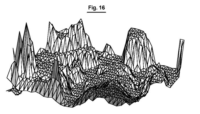
To prevent a polygon from blending in with its neighbors in a system with a limited number of bits per pixel, polygons can be drawn so that its edges are a different color or shade from its interior. An example of this is shown in Fig. 16. (The bands in some of the polygons are artifacts from scan conversion.)
The matrix notation for:
X' = Ax * X + Bx * Y + Cx * Z
Y' = Ay * X + By * Y + Cy * Z
Z' = Az * X + Bz * Y + Cz * Z
is
Conventional Computer Graphics generally uses the form:
and would yield the same result.
The reason is that for matrices A, B, and C
(A*B)Transpose = (B Transpose) * (A Transpose)
Therefore if C = A * B then (C Transpose) = (B Transpose) * (A Transpose)
and
The form used by Conventional Computer Graphics is easier to type but the form I use retains a closer correspondence between the orientation of the matrix coefficients and that of the original equations.
Matrix notation is, after all, only a shorthand for representing simultaneous equations.
For:

Ax = Ax1*Ax2 + Bx1*Bx2 + Cx1*Cx2
Ay = Ay1*Ax2 + By1*Bx2 + Cy1*Cx2
Az = Az1*Ax2 + Bz1*Bx2 + Cz1*Cx2
Bx = Ax1*Ay2 + Bx1*By2 + Cx1*Cy2
By = Ay1*Ay2 + By1*By2 + Cy1*Cy2
Bz = Az1*Ay2 + Bz1*By2 + Cz1*Cy2
Cx = Ax1*Az2 + Bx1*Bz2 + Cx1*Cz2
Cy = Ay1*Az2 + By1*Bz2 + Cy1*Cz2
Cz = Az1*Az2 + Bz1*Bz2 + Cz1*Cz2
In the following discussion, the numbers are more or less in hexadecimal unless otherwise indicated.
We need to be able to represent 1.0000 because all of the matrix coefficients have values between -1.0000 and 1.0000, and we need to be able to multiply 1.0000 * 1.0000 and get an answer of 1.0000; otherwise the unit vectors will deteriorate very quickly. Since we are doing fixed point arithmetic, one might think that the binary point is imaginary and can be put wherever we want.
That is almost true.
If we do 16 bit two's complement integer multiplication the largest positive number that can be represented is 7FFF (8000 is negative). We might therefore be tempted to let 7FFF represent 1.0000 . In integer multiplication 7FFF * 7FFF = 3FFF0001 . Since we want to end up with the same number that we started with, we could take the most significant word and call it 3FFF.0001 .
But then 1.0000 * 1.0000 would not equal 1.0000 . And it can't be fixed with a shift, either. Shifting left gives us 7FFE.0002 . Now we have 7FFF * 7FFF = 7FFE . It's almost right and might be ok if the errors didn't accumulate as we rotated the unit vectors.
The next choice is 4000 . 4000 * 4000 = 10000000. Using the most significant word gives us 1000.0000; shifting left twice produces 4000.0000 . (In the Star Wars game the "shift left twice" was implemented as two fewer clock cycles in the serial multiplier. )
As a result, 4000 will represent 1.0000 and 4000 * 4000 will yield 4000.
For Sines and Cosines 1.0000 = 16384D so that Sin(a) is actually 16384.D * Sin(a). For example: Sin(0.89525 degrees) is really 16384 * Sin(0.89525) = 256.D which is 0100 Hex. Cos (0.89525.D degrees) is actually 16384 * Cos (0.89525.D) = 16382.D = 3FFE Hex.
We are still free to choose different binary points for other purposes.
For example: 4000 * 4000 = 4000 can be interpreted as 4000 (miles) *
4000 (one) = 4000 (miles). Note that 1/2 of one = 2000 so that 4000 (miles)
* 2000 (one-half) = 2000 (miles). Instead of 4000 miles it could have been
4.000 or 40.00 miles. Or it could have been feet or inches or meters or
furlongs or lightyears.
The key to being able to use 16 bit fixed point arithmetic for the unit vector rotations (where errors will accumulate) is that there are angles whose sines and cosines can be accurately represented as binary fractions.
One example is 0.8952 Degrees which was used in the previous example. The number of good angles is limited but the alternative is to use floating point and/or more bits of precision.
I found the first few Magic Angles using an HP35 calculator. In the early 1980s, Doug Snyder wrote a Fortran program to run on our VAX-11/780. I modified his program to format the output to the form I wanted. Much later, I rewrote it using Borland Turbo C to run under DOS. Recently, I adapted it to run as a Windows Console Application compiled with Microsoft Visual C++.
Here is a sample of the output.
16-bits 0x4000 = 16384
Magic Angles Angular
Error Limit = 0.005000 %
COS SIN ISINE ANGLE(deg) %Error(deg/deg) %Magnitude Error
16382 255.992 256 0.89525642
0.0030521 -0.0000007
16380 362.017 362 1.26609665
0.0045790 +0.0000022
16375 542.983 543 1.89919328
0.0030537 -0.0000034
16354 991.030 991 3.46780721
0.0030074 +0.0000110
16350 1054.967 1055 3.69183785
0.0031041 -0.0000129
16334 1279.023 1279 4.47737570
0.0018070 +0.0000110
16322 1423.999 1424 4.98609928
0.0000989 -0.0000007
16319 1457.976 1458 5.10538374
0.0016273 -0.0000129
16305 1606.994 1607 5.62880539
0.0003496 -0.0000034
16301 1647.075 1647 5.76966484
0.0045495 +0.0000458
32-bits 0x40000000 = 1073741824
Magic Angles Angular Error Limit = 0.000500 %
COS
SIN ISINE ANGLE(deg) %Error(deg/deg) %Magnitude
Error
1073741823 46340.950 46341 0.00247279
0.0001079 -0.0000000
1073741822 65536.000 65536 0.00349706
0.0000000 +0.0000000
1073741821 80264.880 80265 0.00428301
0.0001497 -0.0000000
1073741820 92681.900 92682 0.00494559
0.0001080 -0.0000000
1073741819 103621.514 103622 0.00552934
0.0004688 -0.0000000
1073741818 113511.682 113512 0.00605709
0.0002805 -0.0000000
1073741817 122606.629 122607 0.00654240
0.0003026 -0.0000000
1073741816 131072.000 131072 0.00699412
0.0000002 +0.0000000
1073741815 139022.850 139023 0.00741838
0.0001081 -0.0000000
1073741814 146542.951 146543 0.00781966
0.0000337 -0.0000000
Since Windows ungraciously erases the output as soon as the program
ends, the best way to run it is under Win9x DOS. (Yes, you can call a Windows
Console Application from DOS.) You can also redirect the output to a file.
Just run: mjangle.exe >output.txt
|
|
The smallest Magic Angle using 16-bit integers is 0.636 degrees, which produces an incremental rotation which is too large for a first person game. For Star Wars, Greg Rivera came up with the method of using Magic Tics.
In this method, each object has two sets of Unit Vectors: the Primary Set and the Working Copy.
The Working Copy is rotated by smaller, non-magic angles (Tics) until they add up to a Magic Angle. At that point the Primary Set is rotated by the Magic Angle and then the Primary Set is copied to the Working Set.
With Magic Tics, the Magic Angle of 4.986 degrees is divided into 78 Tics, each representing 0.0639 degrees, and a running sum is kept of Tics for each axis.
1. If the Tic sum is greater than or equal to 78, the Primary Set of Unit Vectors is rotated by 4.986 degrees and the Tic sum is decremented by 78. The Primary Set is then copied to the Working Set.
2. If the Tic sum is greater than or equal to 14, the Primary Set of Unit Vectors is rotated by 0.895 degrees and the Tic sum is decremented by 14. (4.986/78*14= 0.895 degrees which is a very good Magic Angle). The Primary Set is then copied to the Working Set.
3. The Working Set is then rotated by any leftover Magic Tics.
4. Negative values are handled in a similar manner.
This gives very precise control and maintains the integrity of the Unit Vectors. You can fly Star Wars all day and not see any deterioration of the Unit Vectors. (Good work, Greg.)
I'm not sure what Max and Stephanie used in Hard Drivin'/Race Drivin'. They may have used Magic Tics. There was some discussion of periodically re-normalizing and re-orthogonalizing the Unit Vectors. Whatever they used was very effective. You can drive Hard Drivin'/Race Drivin' all day and not see any deterioration of the Unit Vectors. (Good work, Max and Stephanie.)
In a 32-bit system the smallest Magic Angle is 0.00247279 degrees and
the number of Magic Angles is very large, so these methods would probably
not be necessary.
Jed Margolin
San Jose, CA
June 2, 2001 (Revised 6/8/2001)
Send comments to: comments@jmargolin.com