Because the schematics for several of the boards used in Hard Drivin'/Race Drivin' were not published in the game manuals I am posting them here.
The original schematics were B Size (11"x17") so I am posting each one as two 8.5"x11" sheets. The left side of the sheet is first, followed by the right side.
I regret that I am not able to provide very much in the way of support for people wanting to troubleshoot their boards.
Jed Margolin
March 9, 2002
Revised: 3/18/02, 5/10/02, 7/18/02
ADSP Board
The ADSP Board uses an Analog Devices ADSP-2100 in a Pin-Grid Array (PGA) package.
The ADSP II Board is identical to the ADSP Board except it uses the ADSP-2100 in the Plastic-Quad-Flat-Pack (PQFP) package.
ADSP and ADSP II Boards
are electrically and mechanically equivalent.
|
|
DSK Board
The DSK (Driver Speed Kit) Board was used in Race Drivin' only. It contains an AT&T DSP32 Floating Point DSP (ASIC61) to provide for a better car model, as well as extra RAM and ROM, and a Texas Instruments TMS320P15 single-chip DSP (ASIC65) for extra security. Atari called the DSP32C and TMS320P15 ASICxx (or in some places (PLDxx) to disguise the fact that they were commercially available ICs. I doubt it fooled anyone.
The DSP32C was originally made by AT&T for their in-house use. Then they started selling it outside the company. Then they spun off their semiconductor business into Lucent Technologies. They seem to have spun off DSPs into a company called Agere. Unfortunately, the DSP32C seems to have been discontinued. However, the datasheet has been reported found at www.freetradezone.com . (Thank you, Tom.)
The TMS320P15 was (is?) a single-chip version of the TMS32010, the first successful DSP. It had internal EPROM protected by a security bit. Once the security bit was programmed you were not supposed to be able to dump the contents of the EPROM. In the part with a window you could only erase the Security Bit by erasing the EPROM program. We used the part without a window so it could not be erased. (The OTP version was also lots cheaper.)
If you ground pin 4 on the TMS320P15 (signal 'P2') and then reset the chip (turning the game off for a few seconds and then turning it on again will do the trick) the TMS320P15 will send the Atari Games copyright message in Morse code which can be received on a standard AM radio by holding it near the DSK Board. Tune around the AM band to get the best quality signal.
I added this to my Self-Test code so that in the event Race Drivin' was pirated I would be able to tell if the program in the TMS320P15 had been reverse engineered or if the chip's security feature had been hacked. (The Morse code program is not accessible from the game code.)
As far as I know, Race Drivin' was never pirated, although Hard Drivin' was.
The TMS320P15 was used
in another game (Road Riot) that was pirated. When I checked for
the Morse code program in the pirated game, it was played loud and clear.
So much for Texas Instrument's claim that the chip's security was actually
worth a damn.
|
|
Motor Amplifier
After several months looking for a real copy of the Motor Amp, I finally found it! This is the Motor Amp used in the Cockpit versions of Hard Drivin' and Race Drivin'.
The Steering Assembly Troubleshooting Guide in the Hard Drivin' and Race Drivin' game manuals helps you narrow down problems to either the Motor or the Motor Amp and then instructs you to contact Atari Customer Service. That is no longer an option since Atari Games no longer exists except as a game development group for home games. It isn't even called Atari Games; it's called Midway Games West.
First a warning.
The voltages used in the Motor and in the Motor Amp are hazardous.Unless you are experienced working with High Voltages, Don't Try to Fix it Yourself. (You really can kill yourself.) In addition, parts of the Motor Amp are NOT isolated from the power line. Working on these parts of the Motor Amp (especially using line-powered equipment like an oscilloscope) requires the use of an isolation transformer. Because the Motor can draw a Lot of current, the isolation transformer has to be a Big Mother. (Variacs are generally Not isolated.) It's not worth getting injured or killed over a video game.
The Motor Amp is interfaced to the game board through the use of opto-isolators in the digital lines. The Motor Amp board was designed to meet U.L. safety standards for high voltage products.
Start by checking the usual suspects (blown fuses, charred components, the smell of smoke, etc.) as well as whether the Force-Feedback has been turned off in the Disable Broken Controls screen in the Test Menu.
The next thing is to determine if the problem is with the Motor, the Motor Amp, the Motor Position Pot, or the A/Ds.
There is a screen in the Test Menu (Special Functions > Main Board Controls > Steering Wheel) that allows you to select various Motor tests that operate open-loop and do not use the position pot.
If these tests work, you know the problem is not with the Motor or the Motor Amp.
There are other screens to read the pots. The Motor position is read by both the 12-bit A/D and the 8-bit A/D. Both must be working or the program knows there is a problem and turns off the Force-Feedback Steering.
There is also an Operator option to turn off Force-Feedback Steering in Disable Broken Controls.
If the Steering Wheel Tests don't move the Motor, the problem is either with the Motor or the Motor Amp.
1. Make sure the ribbon cable is plugged in correctly with Pin 1 of J15 on the Main Board going to Pin 1 of J6 on the Motor Amp Board.
2. There are jumpers on the Motor Amp Board in case we wanted to operate more than one Motor Amp (I don't think we ever did.) In order for it to work in the game, the jumper must be installed in E1 (the one closest to the connector).
3. A voltmeter across the Motor should tell you if the Motor Amp is producing drive for the Motor. (The Send-Force Tests can be used to output a steady drive.)
4. A good way to test the Motor is to connect a DC voltage across it. (Disconnect it from the Motor Amp first.) I believe the motor is either a 60VDC or a 90VDC motor. However, since 60VDC (or 90VDC) produces full torque. I would guess something lower would work. A 24VAC transformer, when half-wave or full-wave rectified and filtered, will produce about 36VDC. That should be enough to test the Motor. (I would guess a 1000 uF filter capacitor would be sufficient.)
Note that if you rectify and filter the 120VAC line you will get about 160 VDC. That is *way* too much for the Motor.
The motor is a DC motor that uses brushes. When it stops working it is usually because the brushes are either worn out or just plain dirty.
I have brought some brush motors back to life by spraying Contact Cleaner at the commutator and brushes. (These were not Hard Drivin' motors.)
I have taken other brush motors apart (also not Hard Drivin' motors), carefully cleaned the brushes and the commutator, and put everything back. Warning, the brushes in a motor are usually spring-loaded.
I don't know how easily this particular motor comes apart.
There isn't much else to go wrong with a DC motor.
If the brushes are worn out you should be able to buy new ones. I have never had to, so I don't know how that works.
You may be able to find someone in your area who rebuilds electric motors.(Or maybe I'm just dating myself.)
If I had to buy a new Motor, I would figure out exactly who made it and what size it is, and look for it online at places like McMaster-Carr. The last time I tried www.mcmaster.com they were still there.
Sorry, I don't have any extra Motors, just the one in my own game.
5. If the Motor is ok, the next thing to look at is the Motor Amp.
The Motor Amp can be tested without the Motor by connecting a small 120VAC light bulb to the output (25 Watt - 40 Watt) and by jumpering the Thermal Protector. I suggest making your own cable to plug into J2 on the Motor Amp Board. (The wiring diagram in the manual shows it as P222.) Pins 1 and 4 normally go to the Thermal Protector in the Motor. (The Thermal Protector opens up if the Motor overheats.) Therefore, P2 Pins 1 and 4 must be jumpered for the Light Bulb tester.
If all you are going to do is plug in the Light Bulb Tester and look for it to light up during the Send Force Tests, then that's fine.
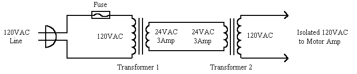
If you are going to troubleshoot the Motor Amp, You Need An Isolation Transformer.
If you don't have an
isolation transformer, you can make your own by connecting two 24VAC 3Amp
transformers back-to-back. This only works if you are using a light bulb
as a load. The Motor draws too much current for this kludge.
At this point you are
on your own. Sorry. (I didn't design the Motor circuit. I just gave Rick
the interface he asked for, and I also wrote the test software for it.)
|
|
[Information on jumpering the Motor
Thermal Protector, the ribbon cable orientation, and the Motor Amp Board
jumpers provided by Tony Rossi. Thank you, Tony.]
The complete set of Hard Drivin' schematics that came in the game manual can be downloaded at: www.spies.com/arcade/schematics/ .
Thanks to the generosity of Bob Langelius I now have a new seat for my Race Drivin' . (One day the bottom of the old seat shattered.)
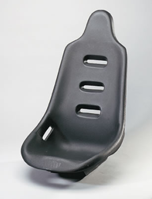
The new seat is from Summit Racing Equipment at www.SummitRacing.com . Warning, their Web site needs some work. The printed catalog is much easier to use.
The catalog number of the seat is SUM-G1100
. Mine is black; they are also available in red, yellow, and blue. They
also have some snazzy looking seat covers for them.
The holes in my new seat do not match the holes in my old seat. I will describe what I did; you may be able to come up with a better method for installing the new seat. (Bear in mind that my game was a preproduction prototype; production games might have been done differently.)
1. I got some new bolts because the mounting nuts in the new seat are bigger than the ones in the old seat. The bolts for the new seat are 3/8 x 16 x 3/4" long. (The old ones were 5/16 x 18 x 3/4" .) I also bought new flat washers and tooth washers for the new bolts. (The store was out of split washers.)
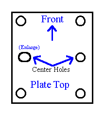
2. My original plan was to drill new holes
in the mounting plate. However, the mounting plate on the seat mechanism
is 3/16" steel which is difficult to work using common tools, so I went
with Plan B which was to enlarge one of the center holes and mount the
new seat with just the two center holes. I did this by drilling an 1/8"
hole (with a sharp drill bit) near the hole I wanted to enlarge and then
using a 3/8" drill bit to enlarge it so that it encroached into the original
hole. Then I used a file to smooth out the resulting elliptical enlarged
hole.
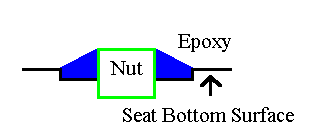
3. In the old seat, the captive mounting nuts appear to be epoxied to the inside bottom surface of the seat and they extend a small distance beyond the bottom side. It appears to be designed to use mounting holes that are large enough to accommodate the nuts and the area immediately around it so that the remaining surface of the seat is supported by whatever it is mounted on. Otherwise, the seat and its occupant are supported solely by the mounting nuts which, under load, could possibly pop out. In any event it would place a great deal of stress around the nuts instead of it being evenly distributed around the larger seat surface.
This is probably why my seat was additionally secured by four toggle bolts through holes in the bottom of the seat.
(The seat bottom has two surfaces: the surface you sit on and the surface that is bolted to the mounting plate, with enough room between them to install a toggle bolt. )
Since I cannot see into the new seat I will assume the captive nuts were done in a simlar way, as opposed to having the mounting nuts attached to a plate inside the seat. (On the other hand, since the seat is intended to be used in a moving vehicle, perhaps the seat can be mounted solely to the nuts.)
To avoid having the seat resting on the captive nuts I placed a sheet of 1/8" hard rubber between the seat and the mounting plate. (I would have used 1/4" hard rubber if I had had it.) As a result, the seat and occupant are supported by the rubber sheet and not by the mounting nuts.
While this method might not withstand heavy
arcade use and probably wouldn't pass the standard shipping drop test,
it's ok for my use. If I ever need to ship it I will strap the seat down
through the slots conveniently placed in the side of the seat.
Plan C would have been to fabricate some kind of adapter bracket. However, that would have been a lot of work. Besides, it would have raised the seat, which I didn't want to do.
Race Drivin' Cockpit EPROMs
and GALs - Final North American Version (Linked Games)
This is for Version 2.4, the final version.
(Please do not ask me for ROM files.)
All ROMs are 137448-200 (27C512,
200 ns) unless otherwise noted.
==================================================================
Main Board:
Loc.
P/N
Chksum ImageFile
Loc. P/N
Chksum ImageFile
210R 136077-5001
$5D01 5001.bin
200R 136077-5002 $F402
5002.bin
210S 136077-5003
$5E03 5003.bin
200S 136077-5004 $8704
5004.bin
210T 136077-5005
$9E05 5005.bin
200T 136077-5006 $7906
5006.bin
210U 136077-4007
$5307 4007.bin
200U 136077-4008 $0608
4008.bin
210V 136077-4009
$FA09 4009.bin
200V 136077-4010 $C110
4010.bin
210W 136077-1011
$5111 1011.bin
200W 136077-1012 $C312
1012.bin
210X 136077-1013
$D613 1013.bin
200X 136077-1014 $F214
1014.bin
210Y 136077-4015
$E215 4015.bi n
200Y 136077-4016 $3C16
4016.bin
Programmed
Board
Part Number
Checksum Location
ImageFile
136077-1021
$6A21 10H
1021.bin
136077-1022
$CB22 10J
1022.bin
136077-1023
$1A23 10K
1023.bin
136077-1024
$A724 10L
1024.bin
Programmed
Board
Part Number
Checksum Location
ImageFile
136077-1028
$8028 30F
1028.bin
136077-1029
$8029 10F
1029.bin
136077-4030
$7E30 30E
4030.bin
136077-4031
$1C31 10E
4031.bin
GALs are GAL20V8, 15 ns
Programmed
User
Board
Part Number
Checksum Signature
Location Function
File
136077-1025 $5133
077-1025 40B
Address Decode dskx1.JED
136077-1026 $50B9
077-1026 60B
Address Decode dskx2.JED
Programmed
Board
Part Number
Checksum Location
Version Function
ImageFile
136077-1032
$A832 70N (RH)
A
Program 1032.bin
136077-1033
$E533 45N (RL)
A
Program 1033.bin
Sound Data Memory is 8 bits.
136052-1123
$EE01 65A (8)
A
Sound Data 65A.bin
136052-1124
$5F02 55A (8)
A
Sound Data 55A.bin
136052-3125
$CC03 45A (8)
C
Sound Data 45A.bin
136052-1126
$2B09 30A (8)
A
Sound Data 30A.bin
136077-1017
$DB09 45C (8)
A
Sound Data 45C.bin
I think the order of the Sound Data
ROMS doesn't matter. Mine are:
136052-1123
$EE01 65A
136052-1124
$5F02 55A
136052-3125
$CC03 55C (45A)
136052-1126
$2B09 65C (30A)
136077-1017
$DB09 45C
Self-Test may think there are supposed
to be 6 ROMS. It is wrong.
GALs are GAL16V8, 25 ns
Programmed
User
Board
Part Number
Checksum Signature
Location Function
File
136052-1139
$6739 052-1139
95A Address Decode
sndx1.JED
136052-1140
$59E0 052-1140
95C Address Decode
sndx2.JED
Generally, 136052-xxxx
was
Hard Drivin' Cockpit
136091-xxxx was
Hard Drivin' Compact
136088-xxxx was
Panorama
136077-xxxx was
Race Drivin' Cockpit
136078-xxxx was
Race Drivin' Compact
Using Hard Drivin' Cockpit as an example:
136052-nxxx where 'n' was the version number
For example:
136052-0xxx was a pre-production prototype
136052-1xxx
was the first released version. This number increased every
time a new version was released.
136052-xxnn
where 'nn' was which ROM it was in
the game. (If there had been more than 99 Programmed parts in the game
we would have had a problem.)
136052-xnxx where n was the World Version Number. For example, 136052-x0xx was the North American Version.
There were four versions that I know about.
In the following, the '?' is probably 1, 2, or 3.
Hard Drivin' Cockpit:
North American - 136052-x0xx
Left Hand Drive, English
UK
- 136052-x?xx
Right Hand Drive, English
German
- 136052-x?xx
LH Drive, German (Game and Self-Test)
Japanese
- 136052-x?xx
Right Hand Drive, Japanese (Game), English (Self Test)
Hard Drivin' Compact:
North American - 136091-x0xx
Left Hand Drive, English
UK
- 136091-x?xx
Right Hand Drive, English
German
- 136091-x?xx
Left Hand Drive, German (Game and Self-Test)
Japanese
- 136091-x?xx
Right Hand Drive, Japanese (Game), English (Self Test)
Race Drivin' Cockpit:
North American - 136077-x0xx
Left Hand Drive, English
UK
- 136077-x?xx
Right Hand Drive, English
German
- 136077-x?xx
Left Hand Drive, German (Game and Self-Test)
Japanese
- 136077-x?xx
Right Hand Drive, Japanese (Game), English (Self Test)
Race Drivin' Compact:
North American - 136078-x0xx
Left Hand Drive, English
UK
- 136078-x?xx
Right Hand Drive, English
German
- 136078-x?xx
Left Hand Drive, German (Game and Self-Test)
Japanese
- 136078-x?xx
Right Hand Drive, Japanese (Game), English (Self Test)
However, some ROMS were reused and given new part numbers to match the game.
Examples:
Main Board
Race Drivin' Cockpit and Race Drivin' Compact share the following ROMs:
136077-1011 = 136078-1011
136077-1012 = 136078-1012
136077-1013 = 136078-1013
136077-1014 = 136078-1014
Sound Board
All the ROMs on the Race Drivin' Compact
Sound Board are identical to the Sound Board ROMs on Race Drivin' Cockpit.
The final version should be backwards compatible with all previous versions.
DSK Board
The Cockpit ROMs 136077-4030 and 136077-4031 do not match the 136078-1030 and 136078-1031.
On Race Drivin' Cockpit the ROMs 136077-1028 and 136077-1029 contain encrypted data for a security program that was not used. The ROMs were inadvertantly left on the parts list so the game was built and shipped with them. The ROMs do not appear to be on the Compact Version.
A similar thing happened with the ZeroPower
RAMs on the DSK Board. They were intended to save the challenge races of
the winning players but we ran out of time so it was not implemented.
Please send comments to: comments@jmargolin.com
Copyright 2002 Jed Margolin