![]() Home |
Lists |
Deathskull Labs |
Museum |
Links
Home |
Lists |
Deathskull Labs |
Museum |
Links
![]() Home |
Lists |
Deathskull Labs |
Museum |
Links
Home |
Lists |
Deathskull Labs |
Museum |
Links
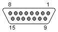
15-pin female D-sub connector on the computer.
15-pin male D-sub connector on the controller.
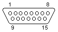
All GND pins are the same. All 5V sources are the same
Potentiometer inputs are 0-100kohm, linear. Directional inputs are read by a RC delay circuit, i.e. the time it takes a capacitor to recharge after being discharged determines the potentiometer positions.
Button inputs have their pins held high by the computer, and are pulled low by the joystick when activated by the user.
Jay Tilton
06/28/98