How Atari Signature Analysis Works
Written by Phillip Eaton - phil@pjeaton.demon.co.uk
*Comments and feedback welcome & appreciated*
Revision 1 - 1999-12-26
Ever wondered what all those 4‑digit ‘signatures’ are, that are dotted around the Atari circuit diagrams? They are used for diagnosing game PCB faults with an Atari CAT Box. They are useful because, armed with a CAT Box and a game PCB and no technical knowledge (so Atari say) you can diagnose most PCB faults down to IC level. Atari have issued signature analysis information for their game PCBs since Battlezone.
How is a signature created? If you send a known stream of data through a game board starting from the processor address bus, the data will ripple through the circuits in a repeatable pattern. By testing for that pattern at various locations against the known patterns - the Atari-provided signatures - you can isolate component faults.
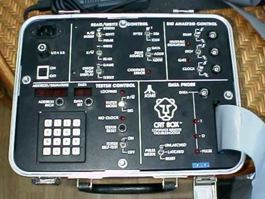
So what’s a CAT Box, then? A CAT Box is a Computer Assisted Troubleshooter, which is in a box. This was manufactured and sold by Atari from 1981 (See Figure 1). To use the CAT Box, you remove the game PCB processor, and plug a connector from the CAT Box onto the game, using the ribbon connector and plug. On the older Atari PCBs, e.g. Missile Command, Centipede, the plug connects to a 50‑way fine‑pitch edge connector. On newer games, e.g. those using a Z80 such as Dig Dug, there is a convertor ‘Pod’ which is also required, which plugs into the processsor socket - see later.

Figure 1. Atari CAT Box Control Panel
Basically, the CAT Box has it’s own processor which then can control the game PCB address & data bus, using the PCB’s clock signal. It can then be used to address individual areas of the board for checking individual components, using the knobs and switches on the CAT Box control panel.
So now you know what a CAT Box is, you have a problem - you don’t have one. So why should you bother reading any further? Well, you might want to read on because you’re interested, but there are other reasons. Although the CAT Box is a 6502 processor‑based piece of kit, the signature analysis bit is almost totally separate from the processor, and you could implement it quite easily with some simple discrete 74‑series logic counters and buffers, and some seven‑segment LED’s.
As well as faultfinding PCBs, signature analysis is especially useful for checking out the integrity of ROM images for games - all you need is eight 4‑hexdigit signatures, and the image to test.
The ROM-IDENTifier program written by Lescot Thierry uses this information in reverse. By using a 32‑bit signature created from a ROM, it then looks up the signature in its database of known signatures and thus can identify which ROM you have just tested. (However, if your image is corrupt, it will not be identifiable.)
The easy and absolute way to check the integrity of an image is to do a binary compare of the sources using Windiff.EXE or MS‑DOS FC.EXE, but you might not have a known‑good image...
Signature analysis relies on the same mathematical theory as Cyclic Redundancy Checking (CRC). A signature is pretty much the same thing as a Cyclic Redundancy Checksum. In my experience, this is used in communications systems to check for integrity of received data at the end of a communication link.
The general idea is to feed the data you want to send through a CRC creator as you are sending it, and then append the calculated CRC to the end of the message. Then, as the receiver reads the data, it also runs it through the CRC creator. If the calculated CRC and received CRCs are the same, the data has transferred correctly.
The CRC creator can be implemented in software, as is usual in data communications, or hardware, as in the case of the CAT Box.
Firstly, there is a 16‑bit counter which is connected to the address bus and, when enabled by the CAT Box processor, continually cycles around the address space from $0000 to $FFFF. This is shown in Figure 2.
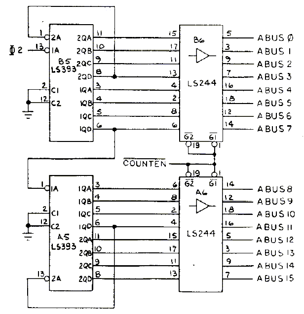
Figure 2. CAT Box Counter Circuitry
This is implemented by four cascaded 4‑bit counters on two 74LS393 ICs. The 74LS244 ICs are used as buffers onto the address bus. (Note there appears to be a bug in the Atari diagram - the second counter on IC B5 appears to be cascading itself! If you understand the diagram, you should be able to spot the easy fix.)
Why is discrete hardware used to cycle round the address bus, when the CAT Box has its own 6502 processor, and can address all of the PCBs address space anyway? This is due to the way that the signature checking works - see further on.
The next part of the circuit is the Start, Stop, Clock and Data probe inputs, shown in Figure 3 and Figure 4.
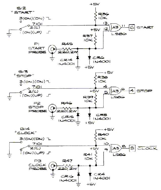
Figure 3. Start, Stop and Clock Probes
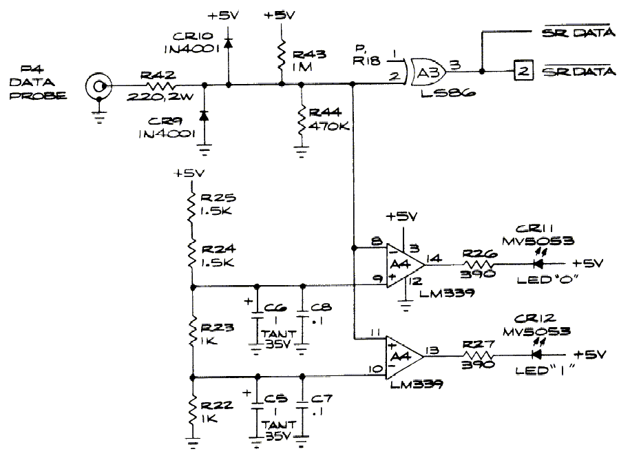
Figure 4. Data Probe
Consider the case where you want to check the signature of a ROM that is still plugged into the PCB. This IC will occupy a certain position in the address space of the PCB. When the 16‑bit address counter cycles through the address space, for a period, the ROM will be enabled and then disabled. This will happen once per cycle of the counter.
When testing the signature, you would connect:
Note that the Data probe is also used as a logic probe by the CAT Box hardware through the LM339 comparitors and the ‘0’ and ‘1’ LED’s.
Using D-Type latches, the Start and Stop probes control the Run/Stop signal that engages the signature analysis calculation hardware.
We can see now why the processor cannot be used to address each location and and test individually. Using the processor would involve using the address and data lines for the instruction fetch & execute cycle, which would reset the Start and Stop part of the circuit, and thus would confuse the signature.
Whilst the ROM under test is enabled the Start and Stop probes allow the LS193 counter to be clocked by the Clock probe. This circuitry is shown in Figure 5.
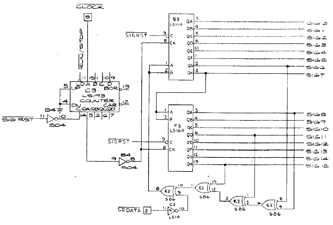
Figure 5. Signature Loop
The data held in the shift register(s) is fed back through XOR gates together with the SRDATA signal to create a new piece of data that is then shifted in to form a new signature.
At the end of each cycle (I guess) the processor reads the SIG0 to SIG15 lines which form a 16‑bit (four hex digit) signature, and updates the seven‑segment display on the CAT Box control panel. Then, the SIG RST line would be used to reset the LS193 counter.
To prove my understanding of this theory, I knocked up a little program that emulates the Signature Analysis bit of the CAT Box circuit.
OK, I know it’s not exactly MAME, but to my surprise, when I wrote it, it worked first time! (If you’ve ever written a CRC checking program, you’ll know that they’re difficult to test, because until you’ve got it right, the results are completely wrong, and offer no clues as to why.)
I used QBasic because:
1. Everyone has a copy of it somewhere so I can provide the source code and you can run it and muck about with it if you want. (Credit my original though, please.)
2. It’s quite easy to understand.
3. I wrote the program in the middle of the desert (literally) and it’s all I had with me at the time.
This is shown in Table 1 Signature Analysis Emulation Program. Copy the code
to a file, call it ATARICRC.BAS or something, and open it with QBasic and run
it with Shift and F5.
''''''''''''''''''''''''''''''''''''''''''''''''''''''''''''''''''''''''''''' ' Atari Signal Analysis for ROM Images Emulator Program ' ' Written using Microsoft MS-DOS QBasic Version 1.1 ' ' Written by Phillip Eaton 1999-12-18 ' mailto:phil@pjeaton.demon.co.uk ' http://www.pjeaton.demon.co.uk ' *Comments and feedback welcome & appreciated* ' ' Program Description: ' Uses software emulation of Cyclic Redundancy Check method as implemented ' in Atari CATBOX hardware for checking integrity of game ROM images. ' ' How to run: ' From DOS, type QBASIC /RUN ATARICRC and press Return. ' Whilst in QBasic, open this file and press Shift+F5. ' ''''''''''''''''''''''''''''''''''''''''''''''''''''''''''''''''''''''''''''' ' Version 1.0 ' Initial Release ' ''''''''''''''''''''''''''''''''''''''''''''''''''''''''''''''''''''''''''''' ' Declare Functions DECLARE FUNCTION CRCBit& (Crc&, NewBit%) DECLARE FUNCTION AtariHEX$ (Crc$) ' Declare Global Constants CONST FALSE = &H0 CONST TRUE = NOT FALSE CONST FILENUMBER% = 1 ' Main program starts here CLS ' Get filename and bit to test from user INPUT "Filename of ROM image |
So you can test it, (Figure 6) shows the codes used for Atari Centipede ROMS (These are extracts from the Signature Analysis Guide to Centipede © 1981 Atari, Inc. document reference TM-192.) I used CENTIPED.210 ROM image for all my tests, and the results show it to be ROM3 (IC J1), as shown in the Figure. (You will need to use your own images.)
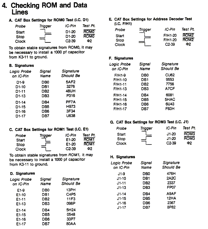
Figure 6. Centipede Signatures
Most of the circuit diagrams for Atari Games have signatures marked on them, but these are usually just logic circuitry signatures, not for the ROM’s. I guess this is so the circuit diagrams were not software dependent, which allowed them to modify the software without invalidating the circuit diagrams that were already released. You’ll need to get your hands on the actual Signature Analysis Guides (or at least the signatures) to check your test results.
Note that the signatures have characters in them that don’t look very hexadecimal. Don’t worry - these are simply substituted for different characters for display by the CAT Box.
See the emulator code for the conversion - it’s very simple. The only reason I can think of for Atari doing this conversion is that they didn’t want any lowercase letters on the seven‑segment display of their CAT Box!
The Atari CAT Box and the signature analysis methods could be used on any manufacturer’s hardware using the same processor - Atari made it simple for owners of their games by adding a dedicated connection point on the side of their PCBs and providing the signatures from known‑working boards.
Atari also produced some ‘pods’ which allowed the CAT Box’s 6502 to control Z80 and other processor‑based hardware. I haven’t seen one of these yet (soon!), but I guess these were used to modify the read/write control line format. This differs slightly between the different types of processor used at the time.
My Dig Dug board, which has 3(!) Z80 processors, doesn’t even have the 50‑way connector, so I guess the CAT Box will need to be connected through the processor socket.
If you wanted to use it on a non‑Atari PCB, you would need to make a connector that would attach your external circuitry in place of the processor. (You need to remove the processor anyway when using the CAT Box.)
The CAT Box was designed when a 6502 was the Dog’s B*’s, no one had a PC and RAM cost a bomb. Through new technology, there is at least one development underway which will re-create and improve the functionality of the CAT Box. Watch this space -
Checkout the Atari CAT Box
User Guide:
CATbox.pdf
Get Lescot Thierry’s ROM-IDENTifier program:
http://www.system16.com/romident.html
© Phillip Eaton 1999-12-26 - ‘Support Your Hobby - Give something back!’