PLEASE NOTE THIS PAGE IS VERY MUCH A WORK IN PROGRESS
BEFORE I START CAN I JUST ASK THAT IF YOU OWN ONE
OF THESE, AND EVEN BETTER STILL HAVE ANY INFORMATION OR DOCUMENTATION ON
IT'S USAGE OR HISTORY YOU
GET IN TOUCH! - THANKS
Jump straight to the pinouts
This "little" item came my way on one of the deals I did over in Holland back
at Christmas last year. It's taken me a long time to get round to doing
anything very much with it, but at long last i've made a start!
I was offered this at a fairly small price due to the person
who was offering it knowing nothing about it's origins, what it did, and
therefore whether it even worked. Put simply it was something that a contact of
his had lying around and due to it's weight and size, basically wanted it out of
the way... So, it was discussed, pictures were exchanged, and although, like the
seller I could still only speculate as to exactly what it was or any of the
origin about it, for some reason i was getting very excited about it! I think i
figured it would be an excellent collectible even if it didn't work, and a major
bonus if it did.
All i knew on purchase was what i was able to sit down and work out with the
seller just before i loaded it into the van, and that was that it seemed to do
"something" :o) In other words, we plugged it in, stood back, flicked the switch
and the cooling fan came to life! That was enough for me and it got included in
that van load...
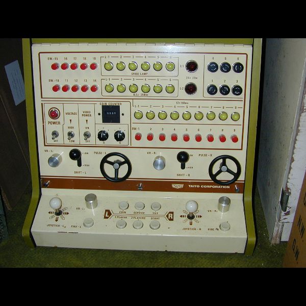
Now obviously it DOES work hence this page has come about. I'll cut the
crap now and get to a bit of the meat of this page. Clearly it is a test rig of
some kind, but exactly what it's capabilities are, i don't know. It has MANY
more controls than i currently know how to use. It is clearly an official
product of the Taito camp and i would guess it originates from the late 70's,
but certainly my example has no plate giving a serial number, model number or
anything, hence anything more than that is still a mystery.
At the moment i use it as a jamma test rig. This culd be considered
sacriledge, but i have not butchered it in any way shape or form in order to
get there. My interest lies firmly in pre-jamma era games and i therefore don't
care that it only has one fire button per player, afterall i have a jamma cab if i want to test more buttons than that.
Right then, features i know so far:
- Operates on line voltages of 100/120/220/240V. These are selected by
moving the position of a "plug" on the side of the unit.
- Powers a monitor directly, supplying what i assume SHOULD be isolated
110V. NOTE: On my unit the 110V is definately NOT isolated, but there has been
a
certain amount of hackery inside. There are two transformers inside the unit so
i can only assume the 110V was once upon a time isolated. I get around this by
running the entire setup from a 1000VA transformer. The power for the monitor is switched independantly from the main unit via the video on/off switch on the
front of the unit. This is essential in order to not kill the monitor as you
find yourself switching the main unit on and off very regularly when trying to
fix boards!
- It has a built in pattern generator and you can switch the video output
from passthrough to internal pattern using a switch on the side. The pattern is
selectable via a bank of dipswitches on the internal pattern generator board.
- When using the internal video board (I bypassed mine at the toggle
switch due to faults) horizontal adjustment of the sync is provided by a
rotary control on the side. There is also a toggle switch to override the
control presumably passing the horizontal part of the sync straight through.
NOTE: I know considerably more about these things now than i did when i first worked out the pinouts (see below) so there may be more to this than meets the eye.
- Provides AT LEAST composite sync and an RGB raster video signal, as mentioned above, it may provide more! I THINK it also supplies a black and white signal through the video output plug too, but i don't know how to test for this at the moment. Rumour has it, it may also provide X/Y/Z outputs for vector displays. If it does, i suspect it will only be black and white. There's NO WAY this unit is "recent" enough to output color vector signals surely???
- "Banana plug" outputs on the side for GND, +5/+12/-5V DC presumably for
use with test equipment.
- Six unswitched two pin power outlets. These supply whatever voltage you put in on the voltage selector plug. WARNING: These are ALWAYS live regardless of whether the main power switch is on or off as long as power is on at the wall outlet. Wanna know how i know? Well, let's just say i found out while exploring the inside to try and work out some of the pinouts :o) Ouch!
- Can provide amplified or unamplified (passthrough) sound. Selectable via a toggle switch and volume control arrangement on the side.
Well, that's what i know so far...
I know NOTHING about what the huge array of buttons and lights do on the
front of the unit. It has been suggested that it is capable of diagnostic
functions, but i have no idea whatsoever how to go about even investigating this
one. The wheels and shifters are fairly obvious as they are identical to those
used on the cocktail version of Taito's Speed Race game from this era. The
rotary controls are i guess paddle controls ALA breakout games, but why there
are four i don't know. I also don't know the pinouts for these extra controls.
Ahhh, pinouts :o) Well, i guess if you own one of these units (i know of
four more in existance, and there must be MANY more!) and you've got this far
then that's obviously what you're after... well, sorry it's 2am UK time now
and i need sleep so you'll have to wait until the next page installment. Don't
panic though it will certainly be in the next couple of days, and probably
tomorrow. I'm on a roll, i have it all written down (as much as i know), it just needs typing in.
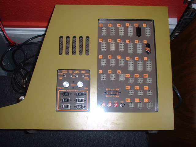
Just for good measure and to make a little sense of what has been said so
far, here is a picture of the side of the unit. Incidentally, these pics are
from prior to me buying the machine. I'm in the process of sorting out some
better ones, but priority one is the pinouts as i've specifically been asked for them!
Copyright © by Guddlers Domain All Right Reserved.