2.
Problem: P1/P2 Blink Flash. No Game Play
When the machine is
turned on, the lighted player one/player two buttons blink/flash, and the
game continually resets or basically looks like its doing nothing.
The spot killer is lit.
a. Fix: Check the power
supply, the large capacitor sometimes comes loose, you'll have to remove
it from the cabinet to check it from the bottom.
b. Fix: When my board
had that problem, it turned out to be loose caps on the board. Specifically,
the largish ones on the right upper side. They mostly have to do with the
sound FX circuits. But, if they come loose and make/break contact, they
send surges that reset the board. The other suggestions I've seen are valid
too. Those caps however, since they stick up off the board, may tend to
get loose first, but you should probably check all solder joints.
3.
Problem: No video, P1 and P2 stay lit. No Game Play
Cause: Connector to
logic board not making good contact with the edge fingers.
Fix: I used a pencil
eraser to clean the fingers. I also noticed that the pins inside the connector
were worn and not making good contact. I used a jewelers screwdriver to
gently put a small bend in each pin. (I really should replace all the pins!)
3a. Problem: No video,
P1 and P2 stay lit, loud humming noise.
Cause: The 5V supply
from the Audio/Reg board was reading about 4.2V
Fix: Replace the LM305
(Q1) regulator, and readjust the voltage.
4.
Problem:
No video, P1 and P2 unlit. No Game Play
Cause: No 5V from the
Audio/Regulator board.
Fix: Replace the 2N3055
(Q3) transistor.
5.
Problem:
Replacing RAM doesn't fix Self test
Initially, the board's
self test reported the fifth RAM in the test (at location N4) to be bad,
so I replaced it. Then it reported the fourth RAM bad (location R4), so
I replaced that. Next, it reported the third RAM (M4) bad, so I replaced
it; however, it still reported M4 bad, so I tried another 2114, with the
same result. However, with a little toggling of switches and probing around,
the RAM failures have inexplicably gone away, and the board now passes
its self test.
Fix: look at your
sockets and make sure they have the same plating as the IC that plugs in
to them. If you have tin-plated leads on an IC plugging into gold plated
socket contacts (or vice versa) you will get some REAL interesting intermittents.
6.
Problem:
The sounds are the same but the objects and the play is approx. 2x as fast.
Fix: See the text
file describing the implemenetation of 2x speedup
and un-do it.
7.
Problem:
The buttons do not work properly
Asteroids Deluxe
recently started having a little intermittent trouble with the buttons.
While rotating and thrusting, pressing fire will interrupt the rotation
of the ship, resulting in no rotate or fire.I put in brand new switch contacts
but once in a while it will still do it. Sometimes it is very often
other times once in a great while. I double checked the wire harness
and
connectors and they seem to be fine. ( .03 ohms from the switch
contacts to the main board and self test seems ok, all switches respond
) Has anyone ever run into this problem? Should I be looking at the inputs
to the J10 and L10 data/sel/multiplexer, or the IC's ? Intermittent
fault makes me think wiring, or switches, or main board connector, or wire
traces on main board.
Fix: It's been three
years since I had a similar problem, so my memory may be
faulty, but check out the POKEY chip. Does
it consistently pass selftest? Replace it and see if your problem
goes away.
Sounds
1.
Problem:
Distorted Sounds
All sounds are there
but the ship fire sound is a high pitched "tink" sound. The sound circuit
looks pretty simple for it and I've changed most of the components
there with no luck.
Fix: Check the capacitors
that stick up all over the board, especially the upper right corner area.
There are quite a few that are for the various sounds, and since they stick
up they tend to work loose.
2.
Problem:
Missing Sounds
Suddenly several of
the game's sound effects have vanished. Specifically, the ship shot, saucer
shot, and saucer flying effects have degraded into various quiet clicks,
pops, and buzzes, though they activate at the proper moments and for the
proper duration's. From looking at the schematics it seems strange to me
that these would all fail simultaneously, while leaving the thump, explosion,
and new life sounds intact.
Fix: 12V regulator had
failed, and was only putting out around 4 volts. This was the cause of
the problems, and was easy to fix.
Missing do,do...do,do sound:
Fix: turned out to be one of those big caps near the upper right corner
of the board had one lead broken. Pretty simple when you know where to
look.
No audio:
Fix: Discovered that
someone had cut the "Disable Audio" trace on the supply/audio board which
disabled the audio amps.
3.
Problem: Lots of Louding Humming
Fix 1:OK you're saying.
Bad 26,000 uF cap in power supply (chassis) which supplies +10.8 volts
unregulated to the amps. Typical problem. Replaced it with a good 30,000
uF cap, hummmmmm....
Fix 2: involves both
replacing the power supply with a switcher and put a better amp in (what's
in there, a wimpy LM386 or something, yes ?).
Fix 3:After trouble-shooting every possible avenue. ( power supply
/ audio board,
speaker and such ) The problem ended up being a bad cap on the logic
board. Now this was a while ago and I don't remember the size of the cap,
but there are four axial caps in the lower-right side of the board ( near
the x and y size adj pots )....One of those caps was the problem.
RESETS
1.
Problem:
Resets Every Couple of Hours Screen Brightness Variation
Asteroids resets itself
every couple of hours. Also, the brightness of the screen varies
constantly. It almost flickers brighter and dimmer. I've found that If
I tap the pcb (in no particular place) the picture gets bright and steady
instantly, but then proceeds to get dimmer and dimmer.
Fix: It was related
to the edge connector. Resoldered the tabs on the pcb where the edge connector
mates with the pcb. This improved contact between the board and the connector,
and the problem went away.
Fix: In soldering, the
pads can lift and be ruined. Why not clean the edge connector and if the
pins in the connector are removable pull them/clean/reopen/replace or just
plain replace pin and if they are not removable use a spring hook tool
(dentist tool) to pry them back toward the center and spray them with a
contact cleaner. BTW: This is the 2nd most common problem in Asteroids/Atari.
Fix: Check the game
board to see if you are getting the proper signals. The test points that
are labeled "X out" and "Y out" are the places to check for vector generation.
If the board isn't supplying from +10V to -10V on the X out or+7.5V to
-7.5V on the Y out, the spot killer circuitry will light the LED on the
monitor deflection board. If there are deflection voltages coming from
the game board, then you will need a more detailed look into the monitor
deflection board. It could be as simple as a blown fuse or transistor.
Gregg Woodcock's XY FAQ is useful even though it is aimed at color XY monitors.
2.
Problem: Random vectors drawn, game resets.
Cause: Oxidation between
ICs and sockets.
Fix: Remove microprocessor
and EPROM's, clean leads with a pencil eraser, reseat in sockets.
Video
1.
Problem:
Picture has a few non visible line shifts in it & grid has jagged lines
The person I bought
it from tried a different board in it and the prob went away. Would this
be a result of a vector generator IC?
If I put the game in
test mode the "chain link fence" looking grid has jagged lines in it where
this screen should have nice 45 degree lines in it as to test for this
type of prob.
Fix: turned out
to be one of the AD651J DACs. I've also had people tell me that a counter
could be the problem.
2.
Problem:
Characters at the very top/bottom of the screen are distorted.
Cause: Y-axis deflection
transistors (Q608, Q609) on Electrohome deflection PCB degraded (?).
Fix: Swap Q708 and Q608,
Q609 and Q709 as a test, or just replace Q608 (2N3716) and Q609 (2N3792)
(?).
3.
Problem:
asteroids and ship, etc. look messed up
When I put the
game into test mode, the cross-hatch is not quite right.. it looks sort
of like this:
__________________
| \ /\ /\ /\ /\ /\ /\ /\ /\ /|
| / \ /\ /\ /\ /\ /\ /\ /\ /\ |
| \ /\ /\ /\ /\ /\ /\ /\ /\ /|
| /\ /\ /\ /\ /\ /\ /\ /\ /\|
notice that the points
where the zig-zags are supposed to meet, they do not...there's an obvious
"gap"...The box around the cross-hatch looks fine.. the 0's (zeros) inside
the box are fine, too... it's just the cross hatch that's all screwed up
- causing the asteroids and ship, etc. to look messed up, as well.. I know
all the IC's in the AVG section are good... they're all socketed and the
same parts work fine in another board set...
Fix: Try the BIP pots
on the game board.
4.
Problem:
Corrupted Video
Despite the fact that
the self test thinks nothing is wrong, the board's video output is very
corrupted. It appears that the X-axis is being properly reproduced, but
vertically the vectors are distorted and only seem to appear in five
horizontal strips, each about 1 cm tall. This makes the self test crosshatch
appear as several strips of saw-toothed lines. The game logic works fine,
as a game can be played and heard normally, albeit with corrupted video.
Fix: The problem was
in the y axis counter on the logic board. Replace all the ALS191's in the
y axis circuitry (I think there are 3). Another tip is to go to Radio
Shack and buy a can of freeze spray. While the game is on and someone
is watching the screen give each chip in the y axis circuitry area a good
blast one at a time. If anything on the screen changes at all, replace
the chip. I found my bad chip by holding my finger on each chip on the
board (hold it on for about 10 seconds), if any logic chip is warm, replace
it.
Fix: Sounds to
me like you have a bad D-A converter. But maybe you only have a few missing
address lines to the D-A. The least significant 8 lines to the D-A come
from a 74LS374 latch at location B10 (-01 thru -04 status board) or B11
(-05 or -06 board). It could also be the 74LS157 multiplexer chip at location
B/C10 (-01 thru -04) or B/C11 (-05 & -06).
5.
Problem:
fold over on both left and right edges.
Fix: Reduce the X output
on the main pcb. Tiny pot, labeled X size. Flip the black slide switch
into the test mode (located on too of the cash box, or on the right side
of the inside wall of the cabinet) this will give you a cross hatch pattern
inside a box. Adjust the box so it just touches the edges of the picture
tube. The "BIP" adjustments ensure that the lines are correct diagonally...
It NORMALLY does is
put up a bunch of cross hairs, which has significantly more white than
a game being played. What you will see when you switch it into test mode
(with the broken Asteroids board) is a more intense white beam across the
bottom of the screen. My Asteroids board has this EXACT problem, and it
turned out to be two problems: A Bad TLO 82 on the output stage of
the Y drive circuit and a bad DAC. That fixed the problem when I replaced
these two parts. The DAC is also hard to measure because it's a current
drive instead of a voltage drive DAC.
6.
Problem:
Ships & Saucers too large on Deluxe:
From: Ben Cole:
Fix: Replacing the M6
(74LS175N Quad D flip flop ) solved the problem. M6 receives the scaling
signals from K6 memory data latch. Special thanks to Jess Askey, jess@magenta.com
for helping me with that problem.
7.
Problem:
Brightness fads out:
From( RGVAC posting):
jamessweet@hotmail.com
Fix: Watch the filement
in the CRT, if it's dimming when the picture fades,
you probably have a
bad connection, or possibly a failing tube, but the
connection is more
likely. <ED> Otherwise if filement stays on maybe PCB.
8.
Problem:
Fluctuating Picture and squeel:
From (vector list):
Fix(suggested not tested):
Have you checked the HV diode between the transformer and the picture tube
? Use Freeze spray on it -- if it works, that's the problem.


 Control
Panel (CPO)
Control
Panel (CPO)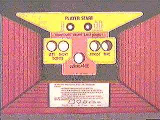 Clone
(Willis) CPO
Clone
(Willis) CPO